Jeep XJ. Manual - part 104


  Index      Jeep     Jeep XJ - service repair manual 2001 year


Search            


Content   ..  102  103  104  105   ..


Jeep XJ. Manual - part 104


(4) Remove the odometer reset knob boot by pull-

ing it out of the cluster lens.

CLUSTER HOOD AND MASK

(1) Disconnect and isolate the battery negative

cable.

(2) Remove the instrument cluster from the instru-

ment panel. Refer to Instrument Cluster in the
Removal and Installation section of this group for the
procedures.

(3) Remove the cluster lens from the cluster hous-

ing. Refer to Instrument Cluster Components -
Cluster Lens 
in the Removal and Installation sec-
tion of this group for the procedures.

(4) Work around the perimeter of the cluster hous-

ing to disengage each of the latches that secure the
cluster hood and mask unit to the cluster housing
(Fig. 14).

(5) Gently pull the cluster hood and mask unit

away from the cluster housing.

CLUSTER HOUSING REAR COVER

(1) Disconnect and isolate the battery negative

cable.

(2) Remove the instrument cluster from the instru-

ment panel. Refer to Instrument Cluster in the

Removal and Installation section of this group for the
procedures.

(3) Work around the perimeter of the cluster hous-

ing to disengage each of the latches that secure the
rear cover to the cluster housing (Fig. 14).

(4) Gently pull the rear cover away from the back

of the cluster housing.

INSTALLATION

CLUSTER BULB

This procedure applies to each of the incandescent

cluster illumination lamp or indicator lamp bulb and
bulb holder units. However, the illumination lamps
and the indicator lamps use different bulb and bulb
holder unit sizes. They must never be interchanged.
Be certain that any bulb and bulb holder unit
removed from the cluster electronic circuit board is
reinstalled in the correct position.

CAUTION: Always use the correct bulb size and
type for replacement. An incorrect bulb size or type
may overheat and cause damage to the instrument
cluster, the electronic circuit board and/or the
gauges.

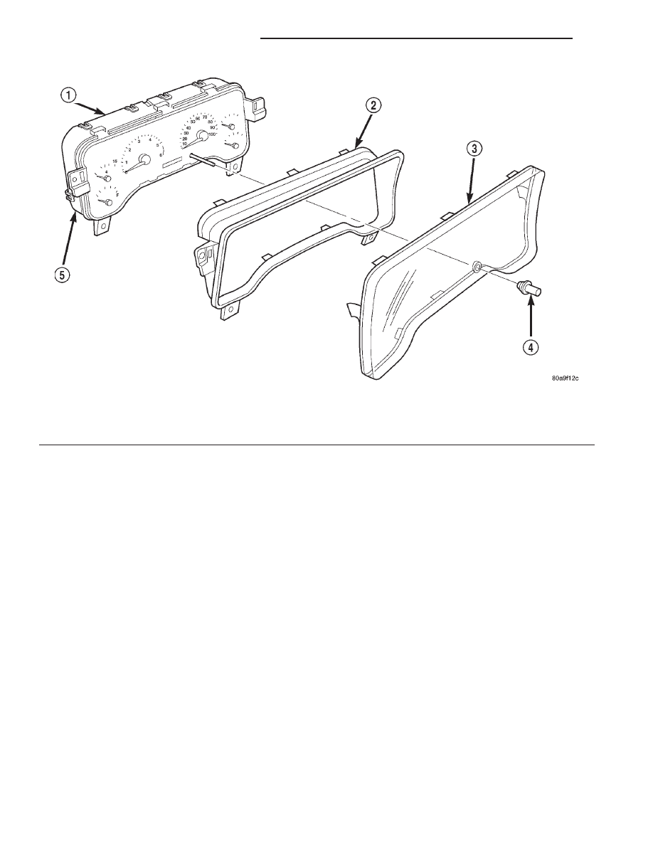
Fig. 14 Instrument Cluster Components

1 – CLUSTER REAR COVER
2 – CLUSTER HOOD AND MASK
3 – CLUSTER LENS

4 – ODOMETER RESET KNOB BOOT
5 – INSTRUMENT CLUSTER HOUSING

8E - 20

INSTRUMENT PANEL SYSTEMS

XJ

REMOVAL AND INSTALLATION (Continued)

(1) Insert the bulb and bulb holder unit straight

into the correct bulb mounting hole in the cluster
electronic circuit board.

(2) With the bulb holder fully seated against the

cluster electronic circuit board, turn the bulb holder
clockwise about sixty degrees to lock it into place.

(3) Install the instrument cluster onto the instru-

ment panel. Refer to Instrument Cluster in the
Removal and Installation section of this group for the
procedures.

(4) Reconnect the battery negative cable.

CLUSTER LENS

(1) Align the cluster lens with the cluster hood and

mask unit.

(2) Press firmly and evenly on the cluster lens to

install it onto the cluster housing.

(3) Work around the perimeter of the cluster hous-

ing to be certain that each of the latches that secure
the cluster lens to the cluster housing is fully
engaged.

(4) Install the instrument cluster onto the instru-

ment panel. Refer to Instrument Cluster in the
Removal and Installation section of this group for the
procedures.

(5) Reconnect the battery negative cable.

ODOMETER RESET KNOB BOOT

(1) Position the odometer reset knob to the mount-

ing hole from the back of the cluster lens.

(2) Pull the odometer reset knob into the mounting

hole from the face of the cluster lens.

(3) Install the cluster lens onto the cluster hous-

ing. Refer to Instrument Cluster Components -
Cluster Lens 
in the Removal and Installation sec-
tion of this group for the procedures.

(4) Install the instrument cluster onto the instru-

ment panel. Refer to Instrument Cluster in the
Removal and Installation section of this group for the
procedures.

(5) Reconnect the battery negative cable.

CLUSTER HOOD AND MASK

(1) Align the hood and mask unit with the cluster

housing.

(2) Press firmly and evenly on the hood and mask

unit to install it onto the cluster housing.

(3) Work around the perimeter of the cluster hous-

ing to be certain that each of the latches that secure
the hood and mask unit to the cluster housing is
fully engaged.

(4) Install the cluster lens onto the cluster hous-

ing. Refer to Instrument Cluster Components -
Cluster Lens 
in the Removal and Installation sec-
tion of this group for the procedures.

(5) Install the instrument cluster onto the instru-

ment panel. Refer to Instrument Cluster in the

Removal and Installation section of this group for the
procedures.

(6) Reconnect the battery negative cable.

CLUSTER HOUSING REAR COVER

(1) Position the rear cover to the back of the clus-

ter housing.

(2) Press firmly and evenly on the rear cover until

each of the latches that secure the rear cover to the
cluster housing is fully engaged.

(3) Install the instrument cluster onto the instru-

ment panel. Refer to Instrument Cluster in the
Removal and Installation section of this group for the
procedures.

(4) Reconnect the battery negative cable.

INSTRUMENT PANEL TOP COVER

WARNING: ON VEHICLES EQUIPPED WITH AIR-
BAGS,

REFER

TO

GROUP

8M

-

PASSIVE

RESTRAINT SYSTEMS BEFORE ATTEMPTING ANY
STEERING

WHEEL,

STEERING

COLUMN,

OR

INSTRUMENT PANEL COMPONENT DIAGNOSIS OR
SERVICE. FAILURE TO TAKE THE PROPER PRE-
CAUTIONS COULD RESULT IN ACCIDENTAL AIR-
BAG DEPLOYMENT AND POSSIBLE PERSONAL
INJURY.

REMOVAL

(1) Disconnect and isolate the battery negative

cable.

(2) Remove the cluster bezel from the instrument

panel. Refer to Cluster Bezel in the Removal and
Installation section of this group for the procedures.

(3) Using a trim stick or another suitable wide

flat-bladed tool, gently pry the rear edge (farthest
from the windshield) of the instrument panel top
cover up and away from the instrument panel far
enough to disengage the seven snap clip retainers
from their receptacles in the instrument panel (Fig.
15).

(4) Pull the top cover sharply rearwards (away

from the windshield) to disengage the four snap clip
retainers that secure the forward edge of the top
cover from their receptacles in the instrument panel
near the base of the windshield.

(5) Remove the top cover from the instrument

panel.

INSTALLATION

(1) Position the top cover onto the instrument

panel.

(2) Align the four snap clips on the forward edge

(nearest the windshield) of the top cover with the
snap clip receptacles in the instrument panel.

XJ

INSTRUMENT PANEL SYSTEMS

8E - 21

REMOVAL AND INSTALLATION (Continued)

(3) Press firmly downward on the top cover over

each of the four forward snap clip locations until
each of the snap clips is fully seated in their recep-
tacles in the instrument panel.

(4) Align the seven snap clips on the rear edge

(farthest from the windshield) of the top cover with
the snap clip receptacles in the instrument panel.

(5) Press firmly downward on the top cover over

each of the seven rearward snap clip locations until
each of the snap clips is fully seated in their recep-
tacles in the instrument panel.

(6) Install the cluster bezel onto the instrument

panel. Refer to Cluster Bezel in the Removal and
Installation section of this group for the procedures.

(7) Reconnect the battery negative cable.

GLOVE BOX

WARNING: ON VEHICLES EQUIPPED WITH AIR-
BAGS,

REFER

TO

GROUP

8M

-

PASSIVE

RESTRAINT SYSTEMS BEFORE ATTEMPTING ANY
STEERING

WHEEL,

STEERING

COLUMN,

OR

INSTRUMENT PANEL COMPONENT DIAGNOSIS OR
SERVICE. FAILURE TO TAKE THE PROPER PRE-
CAUTIONS COULD RESULT IN ACCIDENTAL AIR-
BAG DEPLOYMENT AND POSSIBLE PERSONAL
INJURY.

ROLL DOWN

(1) Disconnect and isolate the battery negative

cable.

(2) Open the glove box.
(3) Locate the two rubber stop bumpers on the

upper edge of the instrument panel glove box open-
ing (Fig. 16).

(4) Remove the two glove box stop bumpers by

sliding them downward and out of the slots in the
instrument panel upper glove box opening reinforce-
ment.

(5) Roll the glove box downward so that the stops

molded into the glove box bin pass through the stop
bumper slots in the instrument panel upper glove
box opening reinforcement.

(6) Reverse the roll down procedure to roll the

glove box back up into the instrument panel.

REMOVAL

(1) Disconnect and isolate the battery negative

cable.

(2) Remove the three screws that secure the glove

box hinge to the instrument panel lower glove box
opening reinforcement (Fig. 17).

(3) Release the glove box latch.
(4) Remove the glove box from the instrument

panel.

INSTALLATION

(1) Position the glove box to the instrument panel

with the bin inserted in the glove box opening far
enough so that the stops on each side of the glove
box bin are located behind the rubber stop bumpers
located on the instrument panel upper glove box
opening reinforcement.

(2) Align the screw holes in the glove box hinge

with the mounting holes in the instrument panel
lower glove box opening reinforcement.

(3) Install and tighten the three screws that secure

the glove box hinge to the instrument panel lower
glove box opening reinforcement. Tighten the screws
to 2.2 N·m (20 in. lbs.).

Fig. 15 Instrument Panel Top Cover Remove/Install

1 – INSTRUMENT PANEL
2 – TOP COVER
3 – FRONT EDGE
4 – REAR EDGE

Fig. 16 Glove Box Stop Bumpers Remove/Install

1 – GLOVE BOX OPENING UPPER REINFORCEMENT
2 – GLOVE BOX LATCH STRIKER
3 – STOP BUMPERS
4 – GLOVE BOX DOOR

8E - 22

INSTRUMENT PANEL SYSTEMS

XJ

REMOVAL AND INSTALLATION (Continued)

(4) Reconnect the battery negative cable.

GLOVE BOX COMPONENTS

The glove box hinge, bin, inner door and latch are

serviced only as a complete unit. The glove box outer
door and lock cylinder are serviced separately.

WARNING: ON VEHICLES EQUIPPED WITH AIR-
BAGS,

REFER

TO

GROUP

8M

-

PASSIVE

RESTRAINT SYSTEMS BEFORE ATTEMPTING ANY
STEERING

WHEEL,

STEERING

COLUMN,

OR

INSTRUMENT PANEL COMPONENT DIAGNOSIS OR
SERVICE. FAILURE TO TAKE THE PROPER PRE-
CAUTIONS COULD RESULT IN ACCIDENTAL AIR-
BAG DEPLOYMENT AND POSSIBLE PERSONAL
INJURY.

REMOVAL

GLOVE BOX HINGE, BIN, INNER DOOR AND LATCH

(1) Disconnect and isolate the battery negative

cable.

(2) Remove the glove box from the instrument

panel. Refer to Glove Box - Removal in the
Removal and Installation section of this group for the
procedures.

(3) Remove the seven screws that secure the inner

glove box door to the outer glove box door (Fig. 18).

(4) Remove the inner glove box door unit from the

outer glove box door.

GLOVE BOX OUTER DOOR

(1) Disconnect and isolate the battery negative

cable.

(2) Remove the glove box from the instrument

panel. Refer to Glove Box - Removal in the

Removal and Installation section of this group for the
procedures.

(3) Remove the seven screws that secure the inner

glove box door to the outer glove box door (Fig. 18).

(4) Remove the outer glove box door from the inner

glove box door unit.

GLOVE BOX LOCK CYLINDER

(1) Insert the key into the glove box lock cylinder

and turn the lock cylinder to the unlocked position.

(2) Open the glove box.
(3) With the key still in the lock cylinder, insert a

small pin punch or a stiff wire into the lock cylinder
release hole (Fig. 19) and depress the lock cylinder
retaining tumbler.

(4) While holding the retaining tumbler depressed,

rotate the key in the lock cylinder clockwise and
press outward on the back of the lock cylinder from
the inside of the glove box door until the lock cylin-
der comes out of the glove box latch lock cylinder
bore.

INSTALLATION

GLOVE BOX HINGE, BIN, INNER DOOR AND LATCH

(1) Position the inner glove box door unit onto the

outer glove box door.

Fig. 17 Glove Box Remove/Install

1 – GLOVE BOX
2 – LATCH
3 – SCREWS

Fig. 18 Glove Box Components Remove/Install

1 – OUTER DOOR
2 – STOPS
3 – INNER DOOR
4 – LATCH
5 – BIN
6 – HINGE
7 – SCREWS

XJ

INSTRUMENT PANEL SYSTEMS

8E - 23

REMOVAL AND INSTALLATION (Continued)


Content   ..  102  103  104  105   ..