Jeep XJ. Manual - part 101


  Index      Jeep     Jeep XJ - service repair manual 2001 year


Search            


Content   ..  99  100  101  102   ..


Jeep XJ. Manual - part 101


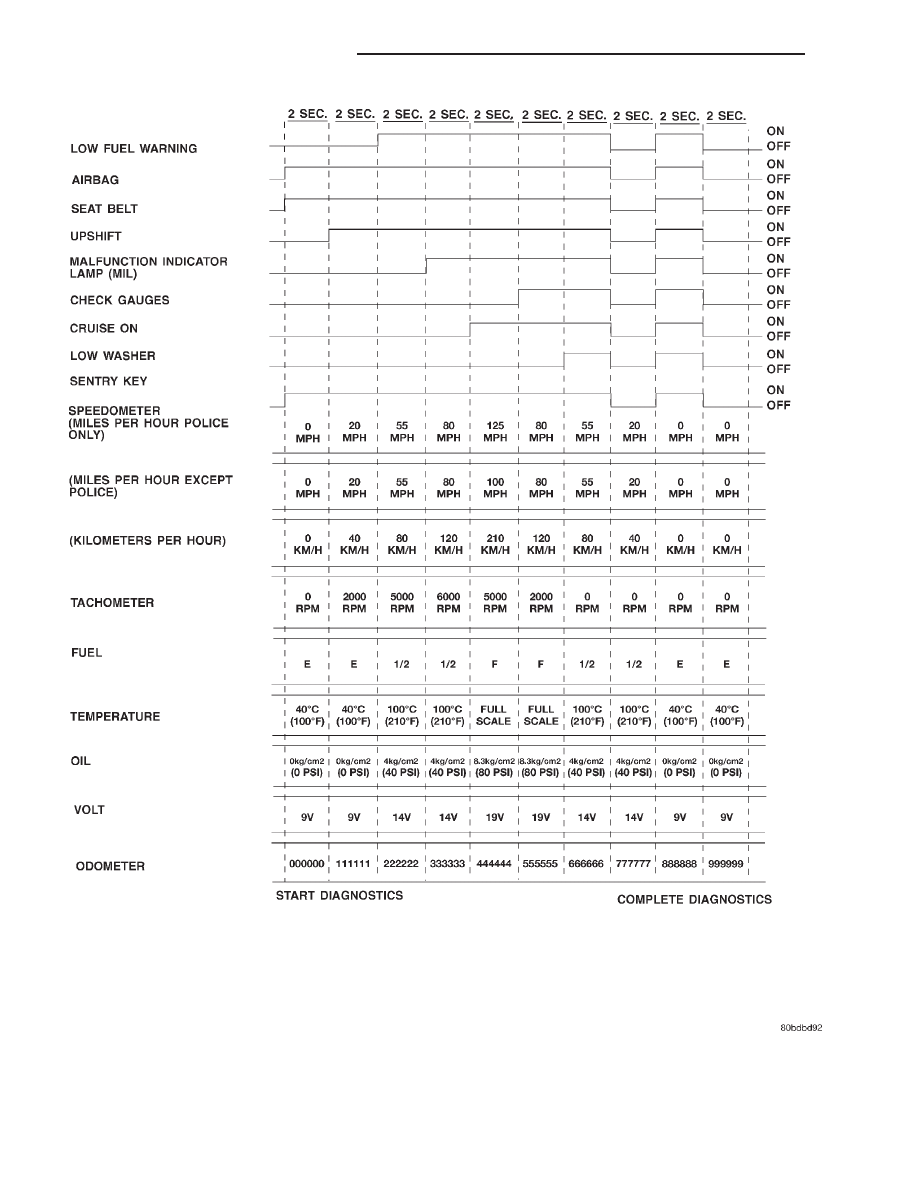
Fig. 2 High-Line Instrument Cluster Actuator Test

8E - 8

INSTRUMENT PANEL SYSTEMS

XJ

DIAGNOSIS AND TESTING (Continued)

BRAKE WARNING LAMP

The diagnosis found here addresses an inoperative

brake warning lamp condition. If the brake warning
lamp stays on with the ignition switch in the On
position and the park brake released, or comes on
while driving, refer Base Brake System for vehicles
not equipped with the four wheel anti-lock brake sys-
tem, or refer to Antilock Brakes for vehicles
equipped with the four wheel anti-lock brake system
in the Diagnosis and Testing section of Group 5 -
Brakes for further diagnosis. If no brake system
problem is found, the following procedure will help
locate a short or open circuit, or a faulty switch. For
complete circuit diagrams, refer to Instrument
Cluster 
in the Contents of Group 8W - Wiring Dia-
grams.

(1) Check the fused ignition switch output (run/

start) fuse in the junction block. If OK, go to Step 2.
If not OK, repair the shorted circuit or component as
required and replace the faulty fuse.

(2) Turn the ignition switch to the On position.

Check for battery voltage at the fused ignition switch
output (run/start) fuse in the junction block. If OK,
go to Step 3. If not OK, repair the open fused ignition
switch output (run/start) circuit to the ignition switch
as required.

(3) Turn the ignition switch to the Off position.

Disconnect and isolate the battery negative cable.
Disconnect the wire harness connector at the park
brake switch. With the park brake released, check for
continuity between the park brake switch terminal
and a good ground. There should be no continuity. If
OK, go to Step 4. If not OK, adjust or replace the
faulty park brake switch.

(4) Disconnect the wire harness connector at the

brake warning switch. Check for continuity between
the two terminals of the brake warning switch. There
should be continuity. If OK, go to Step 5. If not OK,
replace the faulty brake warning switch.

(5) Check for continuity between each of the two

brake warning switch terminals and a good ground.
In each case, there should be no continuity. If OK, go
to Step 6. If not OK, replace the faulty brake warn-
ing switch.

(6) With both the park brake switch and the brake

warning switch wire harness connectors still discon-
nected, check for continuity between the red brake
warning indicator driver circuit cavity of the park
brake switch wire harness connector and a good
ground. There should be no continuity. If OK, go to
Step 7. If not OK, repair the shorted red brake warn-
ing indicator driver circuit as required.

(7) With the ignition switch held in the Start posi-

tion, check for continuity between the red brake
warning indicator driver circuit cavity of the park
brake switch wire harness connector and a good

ground. There should be continuity. If OK, go to Step
8. If not OK, repair the open red brake warning indi-
cator driver circuit to the ignition switch as required.

(8) Turn the ignition switch to the Off position.

Remove the instrument cluster. Check for continuity
between the red brake warning indicator driver cir-
cuit cavity of the instrument cluster wire harness
connector A and a good ground. There should be no
continuity. If OK, go to Step 9. If not OK, repair the
shorted red brake warning indicator driver circuit as
required.

(9) Check for continuity between the red brake

warning indicator driver circuit cavities of the instru-
ment cluster wire harness connector A and the brake
warning switch wire harness connector. There should
be continuity. If OK, replace the faulty bulb. If not
OK, repair the open red brake warning indicator
driver circuit as required.

FOUR-WHEEL DRIVE INDICATOR LAMP - FULL TIME

The diagnosis found here addresses an inoperative

four-wheel drive indicator lamp condition. If the
problem being diagnosed is related to lamp accuracy,
be certain to confirm that the problem is with the
lamp or switch and not with a damaged or inopera-
tive transfer case or transfer case linkage. Refer to
NV242 Diagnosis in the Diagnosis and Testing sec-
tion of Group 21 - Transmission for more informa-
tion. If no transfer case problem is found, the
following procedure will help locate a short or open
in the indicator lamp circuit. For complete circuit
diagrams, refer to Instrument Cluster in the Con-
tents of Group 8W - Wiring Diagrams.

(1) Check the fused ignition switch output (run/

start) fuse in the junction block. If OK, go to Step 2.
If not OK, repair the shorted circuit or component as
required and replace the faulty fuse.

(2) Turn the ignition switch to the On position.

Check for battery voltage at the fused ignition switch
output (run/start) fuse in the junction block. If OK,
go to Step 3. If not OK, repair the open fused ignition
switch output (run/start) circuit to the ignition switch
as required.

(3) Turn the ignition switch to the Off position.

Disconnect and isolate the battery negative cable.
Disconnect the transfer case switch wire harness con-
nector. Check for continuity between the ground cir-
cuit cavity of the transfer case switch wire harness
connector and a good ground. There should be conti-
nuity. If OK, go to Step 4. If not OK, repair the open
ground circuit to ground as required.

(4) Connect the battery negative cable. Turn the

ignition switch to the On position. Install a jumper
wire between the full time four wheel drive indicator
lamp driver circuit cavity of the transfer case switch
wire harness connector and a good ground. The full

XJ

INSTRUMENT PANEL SYSTEMS

8E - 9

DIAGNOSIS AND TESTING (Continued)

time four-wheel drive indicator lamp should light. If
OK, replace the faulty transfer case switch. If not
OK, go to Step 5.

(5) Turn the ignition switch to the Off position.

Disconnect and isolate the battery negative cable.
Remove the instrument cluster. With the transfer
case switch wire harness connector still disconnected,
check for continuity between the full time four wheel
drive indicator lamp driver circuit cavity of the
instrument cluster wire harness connector B and a
good ground. There should be no continuity. If OK, go
to Step 6. If not OK, repair the shorted full time four
wheel drive indicator lamp driver circuit as required.

(6) Check for continuity between the full time four

wheel drive indicator lamp driver circuit cavities of
the instrument cluster wire harness connector B and
the transfer case switch wire harness connector.
There should be continuity. If OK, replace the faulty
bulb. If not OK, repair the open full time four wheel
drive indicator lamp driver circuit as required.

FOUR-WHEEL DRIVE INDICATOR LAMP - PART TIME

The diagnosis found here addresses an inoperative

four-wheel drive indicator lamp condition. If the
problem being diagnosed is related to lamp accuracy,
be certain to confirm that the problem is with the
lamp or switch and not with a damaged or inopera-
tive transfer case or transfer case linkage. Refer to
NV231 Diagnosis or NV242 Diagnosis in the Diag-
nosis and Testing section of Group 21 - Transmission
for more information. If no transfer case problem is
found, the following procedure will help locate a
short or open in the indicator lamp circuit. For com-
plete circuit diagrams, refer to Instrument Cluster
in the Contents of Group 8W - Wiring Diagrams.

(1) Check the fused ignition switch output (run/

start) fuse in the junction block. If OK, go to Step 2.
If not OK, repair the shorted circuit or component as
required and replace the faulty fuse.

(2) Turn the ignition switch to the On position.

Check for battery voltage at the fused ignition switch
output (run/start) fuse in the junction block. If OK,
go to Step 3. If not OK, repair the open fused ignition
switch output (run/start) circuit to the ignition switch
as required.

(3) Turn the ignition switch to the Off position.

Disconnect and isolate the battery negative cable.
Disconnect the transfer case switch wire harness con-
nector. Check for continuity between the ground cir-
cuit cavity of the transfer case switch wire harness
connector and a good ground. There should be conti-
nuity. If OK, go to Step 4. If not OK, repair the open
ground circuit to ground as required.

(4) Connect the battery negative cable. Turn the

ignition switch to the On position. Install a jumper
wire between the part time four wheel drive indicator

lamp driver circuit cavity of the transfer case switch
wire harness connector and a good ground. The part
time four-wheel drive indicator lamp should light. If
OK, replace the faulty transfer case switch. If not
OK, go to Step 5.

(5) Turn the ignition switch to the Off position.

Disconnect and isolate the battery negative cable.
Remove the instrument cluster. With the transfer
case switch wire harness connector still disconnected,
check for continuity between the part time four
wheel drive indicator lamp driver circuit cavity of the
instrument cluster wire harness connector B and a
good ground. There should be no continuity. If OK, go
to Step 6. If not OK, repair the shorted part time
four wheel drive indicator lamp driver circuit as
required.

(6) Check for continuity between the part time

four wheel drive indicator lamp driver circuit cavities
of the instrument cluster wire harness connector B
and the transfer case switch wire harness connector.
There should be continuity. If OK, replace the faulty
bulb. If not OK, repair the open part time four wheel
drive indicator lamp driver circuit as required.

HEADLAMP HIGH BEAM INDICATOR LAMP

The diagnosis found here addresses an inoperative

headlamp high beam indicator lamp condition. If the
problem being diagnosed is related to inoperative
headlamp high beams, refer to Headlamp Diagno-
sis 
in the Diagnosis and Testing section of Group 8L
- Lamps for diagnosis of the headlamp system. If no
headlamp system problems are found, the following
procedure will help locate an open in the high beam
indicator lamp circuit. For complete circuit diagrams,
refer to Instrument Cluster in the Contents of
Group 8W - Wiring Diagrams.

(1) Disconnect and isolate the battery negative

cable. Remove the instrument cluster.

(2) Connect the battery negative cable. Turn the

headlamps on and select the high beams with the
multi-function switch stalk. Check for battery voltage
at the high beam indicator driver circuit cavity of the
instrument cluster wire harness connector A. If OK,
replace the faulty bulb. If not OK, repair the open
high beam indicator driver circuit to the headlamp
dimmer (multi-function) switch as required.

LOW WASHER FLUID WARNING LAMP

The diagnosis found here addresses an inoperative

low washer fluid warning lamp condition. If the prob-
lem being diagnosed is related to lamp accuracy, be
certain to confirm that the problem is with the lamp
or washer fluid level sensor and not with a damaged
or empty washer fluid reservoir. Inspect the reservoir
for proper fluid level and signs of damage or distor-
tion that could affect sensor performance before you

8E - 10

INSTRUMENT PANEL SYSTEMS

XJ

DIAGNOSIS AND TESTING (Continued)

proceed with lamp diagnosis. Refer to Washer Sys-
tem 
in the Diagnosis and Testing section of Group
8K - Wiper and Washer Systems for more informa-
tion. For complete circuit diagrams, refer to Instru-
ment Cluster 
in the Contents of Group 8W - Wiring
Diagrams.

(1) Check the fused ignition switch output (run/

start) fuse in the junction block. If OK, go to Step 2.
If not OK, repair the shorted circuit or component as
required and replace the faulty fuse.

(2) Turn the ignition switch to the On position.

Check for battery voltage at the fused ignition switch
output (run/start) fuse in the junction block. If OK,
go to Step 3. If not OK, repair the open fused ignition
switch output (run/start) circuit to the ignition switch
as required.

(3) Turn the ignition switch to the Off position.

Disconnect the wire harness connector from the
washer fluid level sensor. Install a jumper wire
between the two cavities of the washer fluid level
sensor wire harness connector. Turn the ignition
switch to the On position. About thirty seconds after
the ignition switch is turned to the On position, the
low washer fluid warning lamp should light. Remove
the jumper wire and the lamp should go off. If OK,
replace the faulty washer fluid level sensor. If not
OK, go to Step 4.

(4) Turn the ignition switch to the Off position.

Check for continuity between the ground circuit cav-
ity of the washer fluid level sensor wire harness con-
nector

and

a

good

ground.

There

should

be

continuity. If OK, go to Step 5. If not OK, repair the
open ground circuit to ground as required.

(5) Disconnect and isolate the battery negative

cable. Remove the instrument cluster. The washer
fluid level sensor wire harness connector is still dis-
connected. Check for continuity between the low
washer fluid level sense circuit cavity of the instru-
ment cluster wire harness connector B and a good
ground. There should be no continuity. If OK, go to
Step 6. If not OK, repair the shorted low washer
fluid level sense circuit as required.

(6) Check for continuity between the low washer

fluid level sense circuit cavities of the instrument
cluster wire harness connector B and the washer
fluid level sensor wire harness connector. There
should be continuity. If OK, replace the faulty bulb.
If not OK, repair the open low washer fluid level
sense circuit as required.

TURN SIGNAL INDICATOR LAMP

The diagnosis found here addresses an inoperative

turn signal indicator lamp condition. For any other
turn signal problem, refer to Turn Signal and Haz-
ard Warning Systems 
in the Diagnosis and Testing
section of Group 8J - Turn Signal and Hazard Warn-

ing Systems for further diagnosis. If no turn signal or
hazard warning system problem is found, the follow-
ing procedure will help locate a short or open in the
indicator lamp circuit. For complete circuit diagrams,
refer to Instrument Cluster in the Contents of
Group 8W - Wiring Diagrams.

(1) Disconnect and isolate the battery negative

cable. Remove the instrument cluster.

(2) Connect the battery negative cable. Activate

the hazard warning system by moving the hazard
warning switch button to the On position. Check for
battery voltage at the inoperative (right or left) turn
signal circuit cavity of the instrument cluster wire
harness connector (connector A - left, or connector B -
right). There should be a switching (on and off) bat-
tery voltage signal. If OK, replace the faulty (right or
left) indicator lamp bulb. If not OK, repair the open
(right or left) turn signal circuit to the turn signal/
hazard warning (multi-function) switch as required.

INSTRUMENT PANEL CIGAR LIGHTER

For complete circuit diagrams, refer to Horn/Ci-

gar Lighter in the Contents of Group 8W - Wiring
Diagrams.

WARNING: ON VEHICLES EQUIPPED WITH AIR-
BAGS,

REFER

TO

GROUP

8M

-

PASSIVE

RESTRAINT SYSTEMS BEFORE ATTEMPTING ANY
STEERING

WHEEL,

STEERING

COLUMN,

OR

INSTRUMENT PANEL COMPONENT DIAGNOSIS OR
SERVICE. FAILURE TO TAKE THE PROPER PRE-
CAUTIONS COULD RESULT IN ACCIDENTAL AIR-
BAG DEPLOYMENT AND POSSIBLE PERSONAL
INJURY.

(1) Remove the cigar lighter knob and element

from the cigar lighter receptacle shell. Check for con-
tinuity between the inside circumference of the cigar
lighter receptacle shell and a good ground. there
should be continuity. If OK, go to Step 2. If not OK,
go to Step 3.

(2) Turn the ignition switch to the On position.

Check for battery voltage at the insulated contact
located at the back of the cigar lighter receptacle
shell. If OK, replace the faulty cigar lighter knob and
element. If not OK, go to Step 3.

(3) Turn the ignition switch to the Off position.

Disconnect and isolate the battery negative cable.
Remove the instrument panel accessory switch bezel.
Check for continuity between the ground circuit cav-
ity of the cigar lighter wire harness connector and a
good ground. There should be continuity. If OK, go to
Step 4. If not OK, repair the open ground circuit to
ground as required.

(4) Connect the battery negative cable. Turn the

ignition switch to the Accessory or On positions.
Check for battery voltage at the cigar lighter relay

XJ

INSTRUMENT PANEL SYSTEMS

8E - 11

DIAGNOSIS AND TESTING (Continued)


Content   ..  99  100  101  102   ..