Jeep XJ. Manual - part 96


  Index      Jeep     Jeep XJ - service repair manual 2001 year


Search            


Content   ..  94  95  96  97   ..


Jeep XJ. Manual - part 96


IGNITION COIL—2.5L ENGINE

REMOVAL

The ignition coil is an epoxy filled type. If the coil

is replaced, it must be replaced with the same type.

On the 2.5L 4-cylinder engine, the ignition coil is

mounted to a bracket on side of engine (to rear of
distributor) (Fig. 20).

(1) Disconnect ignition coil secondary cable from

ignition coil.

(2) Disconnect engine harness connector from igni-

tion coil.

(3) Remove ignition coil mounting bolts (nuts are

used on back side of bracket on some coils).

(4) Remove coil from vehicle.

INSTALLATION

(1) Install ignition coil to bracket on cylinder block

with mounting bolts (and nuts if equipped). If
equipped with nuts and bolts, tighten to 11 N·m (100
in. lbs.) torque. If equipped with bolts only, tighten to
5 N·m (50 in. lbs.) torque.

(2) Connect engine harness connector to coil.
(3) Connect ignition coil cable to ignition coil.

IGNITION COIL—4.0L ENGINE

REMOVAL

A one-piece coil rail assembly containing three

individual coils is used on the 4.0L engine (Fig. 21).
The coil rail must be replaced as one assembly. The
bottom of the coil is equipped with 6 individual rub-

ber boots (Fig. 21) to seal the 6 spark plugs to the
coil. Inside each rubber boot is a spring. The spring
is used for an electrical contact between the coil and
the top of the spark plug. These rubber boots and
springs are a permanent part of the coil and are not
serviced separately.

(1) Disconnect negative battery cable at battery.
(2) The coil is bolted directly to the cylinder head.

Remove 4 coil mounting bolts (Fig. 22).

(3) Carefully pry up coil assembly from spark

plugs. Do this by prying alternately at each end of
coil until rubber boots have disengaged from all
spark plugs. If boots will not release from spark
plugs, use a commercially available spark plug boot
removal tool. Twist and loosen a few boots from a few
spark plugs to help remove coil.

(4) After coil has cleared spark plugs, position coil

for access to primary electrical connector. Disconnect
connector from coil by pushing slide tab outwards to
right side of vehicle (Fig. 23). After slide tab has been
positioned outwards, push in on secondary release
lock (Fig. 23) on side of connector and pull connector
from coil.

(5) Remove coil from vehicle.

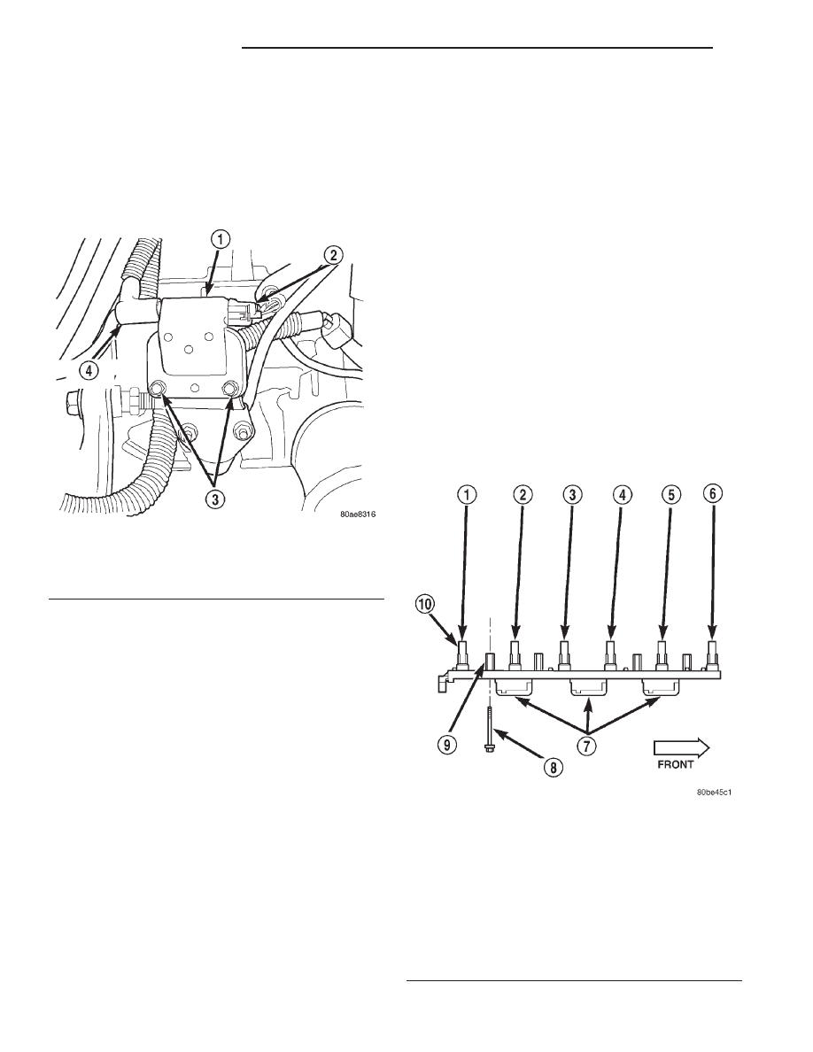
Fig. 20 Ignition Coil—2.5L Engine

1 – IGNITION COIL
2 – ELECTRICAL CONNECTOR
3 – MOUNTING BOLTS (2)
4 – SECONDARY CABLE

Fig. 21 Ignition Coil Assembly—4.0L 6–Cylinder

Engine

1 – CYL. #6
2 – CYL. #5
3 – CYL. #4
4 – CYL. #3
5 – CYL. #2
6 – CYL. #1
7 – COILS (3)
8 – MOUNTING BOLTS (4)
9 – BOLT BASES (4)
10 – RUBBER BOOTS (6)

8D - 12

IGNITION SYSTEM

XJ

REMOVAL AND INSTALLATION (Continued)

INSTALLATION

(1) Position ignition coil rubber boots to all spark

plugs. Push down on coil assembly until bolt bases
have contacted cylinder head

(2) Install 4 coil mounting bolts. Loosely tighten 4

bolts just enough to allow bolt bases to contact cylin-
der head. Do a final tightening of each bolt in steps
down to 29 N·m (250 in. lbs.) torque. Do not apply
full torque to any bolt first.

(3) Connect engine harness connector to coil by

snapping into position. Move slide tab towards
engine (Fig. 23) for a positive lock.

(4) Connect negative battery cable to battery.

CRANKSHAFT POSITION (CKP) SENSOR

REMOVAL

The crankshaft position (CKP) sensor is mounted

to the transmission bellhousing at the left/rear side
of the engine block.

The sensor may be mounted to the transmission

with one of the following three different configura-
tions:

• with one bolt (Fig. 24). If sensor is equipped

with one mounting bolt, it is adjustable..

• with two nuts (Fig. 25).

• with two bolts (Fig. 26).

Fig. 22 Ignition Coil Rail Location—4.0L 6–Cylinder

Engine

1 – COIL RAIL
2 – COIL MOUNTING BOLTS (4)
3 – COIL
4 – COIL ELECTRICAL CONNECTION

Fig. 23 Ignition Coil Electrical Connector—4.0L

6–Cylinder Engine

1 – REAR OF VALVE COVER
2 – COIL RAIL
3 – SLIDE TAB
4 – RELEASE LOCK
5 – COIL CONNECTOR

Fig. 24 Crankshaft Position Sensor—One-Bolt

Mounting

1 – SENSOR PIGTAIL
2 – CRANKSHAFT POSITION SENSOR
3 – MOUNTING BOLT
4 – TRANSMISSION HOUSING
5 – PAPER SPACER
6 – SLOTTED HOLE

XJ

IGNITION SYSTEM

8D - 13

REMOVAL AND INSTALLATION (Continued)

(1) Near left-rear side of engine, disconnect sensor

pigtail harness (electrical connector) from main elec-
trical

harness

connector.

These

connectors

are

attached to a bracket which is attached to the left-
front side of the transmission.

(2) Depending upon application, remove either sen-

sor mounting bolt(s) or nuts.

(3) Remove sensor from engine.

INSTALLATION

Sensor With 2–Bolt Mounting:
(1) Install sensor flush against opening in trans-

mission housing.

(2) Install and tighten two sensor mounting bolts

to 19 N·m (14 ft. lbs.) torque. The two sensor mount-
ing bolts are specially machined to correctly space
unit to flywheel. Do not attempt to install any other
bolts.

Sensor With 2–Nut Mounting:
(3) Install and tighten two sensor mounting nuts

to 19 N·m (14 ft. lbs.) torque.

Sensor With One-Bolt Mounting:
New replacement sensors will be equipped with a

paper spacer glued to bottom of sensor. If installing
(returning) a used sensor to vehicle, a new paper
spacer must be installed to bottom of sensor. This

spacer will be ground off the first time engine is
started. If spacer is not used, sensor will be broken
the first time engine is started.

(4) New Sensors: Be sure paper spacer is installed

to

bottom

of

sensor.

If

not,

obtain

spacer

PN05252229.

(5) Used Sensors: Clean bottom of sensor and

install spacer PN05252229.

(6) Install sensor into transmission bellhousing

hole.

(7) Push sensor against flywheel/drive plate. With

sensor pushed against flywheel/drive plate, tighten
mounting bolt to 7 N·m (60 in. lbs.) torque.

(8) Connect sensor pigtail harness electrical con-

nector to main wiring harness connector.

CAMSHAFT POSITION SENSOR—2.5L ENGINE

On 2.5L engines, the camshaft position sensor is

located in the distributor (Fig. 27).

REMOVAL

Distributor removal is not necessary to remove

camshaft position sensor.

(1) Disconnect negative battery cable at battery.
(2) Remove distributor cap from distributor (two

screws).

(3) Disconnect camshaft position sensor wiring

harness from main engine wiring harness.

Fig. 25 Crankshaft Position Sensor—Two-Nut

Mounting

1 – TRANSMISSION BELLHOUSING
2 – MOUNTING NUTS (2)
3 – CRANKSHAFT POSITION SENSOR
4 – MOUNTING STUDS (2)
5 – RUBBER GROMMET
6 – SENSOR PIGTAIL

Fig. 26 Crankshaft Position Sensor—Two-Bolt

Mounting

1 – TRANSMISSION BELLHOUSING
2 – MOUNTING BOLTS (2)
3 – CRANKSHAFT POSITION SENSOR
4 – RUBBER GROMMET
5 – SENSOR PIGTAIL

8D - 14

IGNITION SYSTEM

XJ

REMOVAL AND INSTALLATION (Continued)

(4) Remove distributor rotor from distributor shaft.
(5) Lift camshaft position sensor assembly from

distributor housing (Fig. 27).

INSTALLATION

(1) Install camshaft position sensor to distributor.

Align sensor into notch on distributor housing.

(2) Connect wiring harness.
(3) Install rotor.
(4) Install

distributor

cap.

Tighten

mounting

screws.

CAMSHAFT POSITION SENSOR—4.0L ENGINE

The Camshaft Position Sensor (CMP) on the 4.0L

6–cylinder engine is bolted to the top of the oil pump
drive shaft assembly (Fig. 28). The sensor and drive
shaft assembly is located on the right side of the
engine near the oil filter (Fig. 29).

The rotational position of oil pump drive deter-

mines fuel synchronization only. It does not deter-
mine ignition timing.

NOTE: Do not attempt to rotate the oil pump drive
to modify ignition timing.

Two

different

procedures

are

needed

for

removal and installation. The first procedure will
detail removal and installation of the sensor only.
The second procedure will detail removal and instal-
lation of the sensor and oil pump drive shaft assem-
bly. The second procedure is to be used if the engine
has been disassembled.

An internal oil seal is used in the drive shaft hous-

ing that prevents engine oil at the bottom of the sen-
sor. The seal is not serviceable.

REMOVAL—SENSOR ONLY

(1) Disconnect electrical connector at CMP sensor

(Fig. 29).

(2) Remove 2 sensor mounting bolts (Fig. 28) or

(Fig. 29).

(3) Remove sensor from oil pump drive.

INSTALLATION—SENSOR ONLY

(1) Install sensor to oil pump drive.
(2) Install 2 sensor mounting bolts and tighten to

2 N·m (15 in. lbs.) torque.

(3) Connect electrical connector to CMP sensor.

REMOVAL—OIL PUMP DRIVE AND SENSOR

If the CMP and oil pump drive are to be

removed and installed, do not allow engine
crankshaft or camshaft to rotate. CMP sensor
relationship will be lost.

(1) Disconnect electrical connector at CMP sensor

(Fig. 29).

(2) Remove 2 sensor mounting bolts (Fig. 28) or

(Fig. 29).

(3) Remove sensor from oil pump drive.

Fig. 27 Camshaft Position Sensor—2.5L Engine

1 – SYNC SIGNAL GENERATOR
2 – CAMSHAFT POSITION SENSOR
3 – PULSE RING
4 – DISTRIBUTOR ASSEMBLY

Fig. 28 CMP and Oil Pump Drive Shaft—4.0L Engine

1 – CAMSHAFT POSITION SENSOR
2 – MOUNTING BOLTS (2)
3 – PULSE RING
4 – DRIVE GEAR (TO CAMSHAFT)
5 – OIL PUMP DRIVESHAFT
6 – SENSOR BASE (OIL PUMP DRIVESHAFT ASSEMBLY)

XJ

IGNITION SYSTEM

8D - 15

REMOVAL AND INSTALLATION (Continued)


Content   ..  94  95  96  97   ..