Jeep XJ. Manual - part 86


  Index      Jeep     Jeep XJ - service repair manual 2001 year


Search            


Content   ..  84  85  86  87   ..


Jeep XJ. Manual - part 86


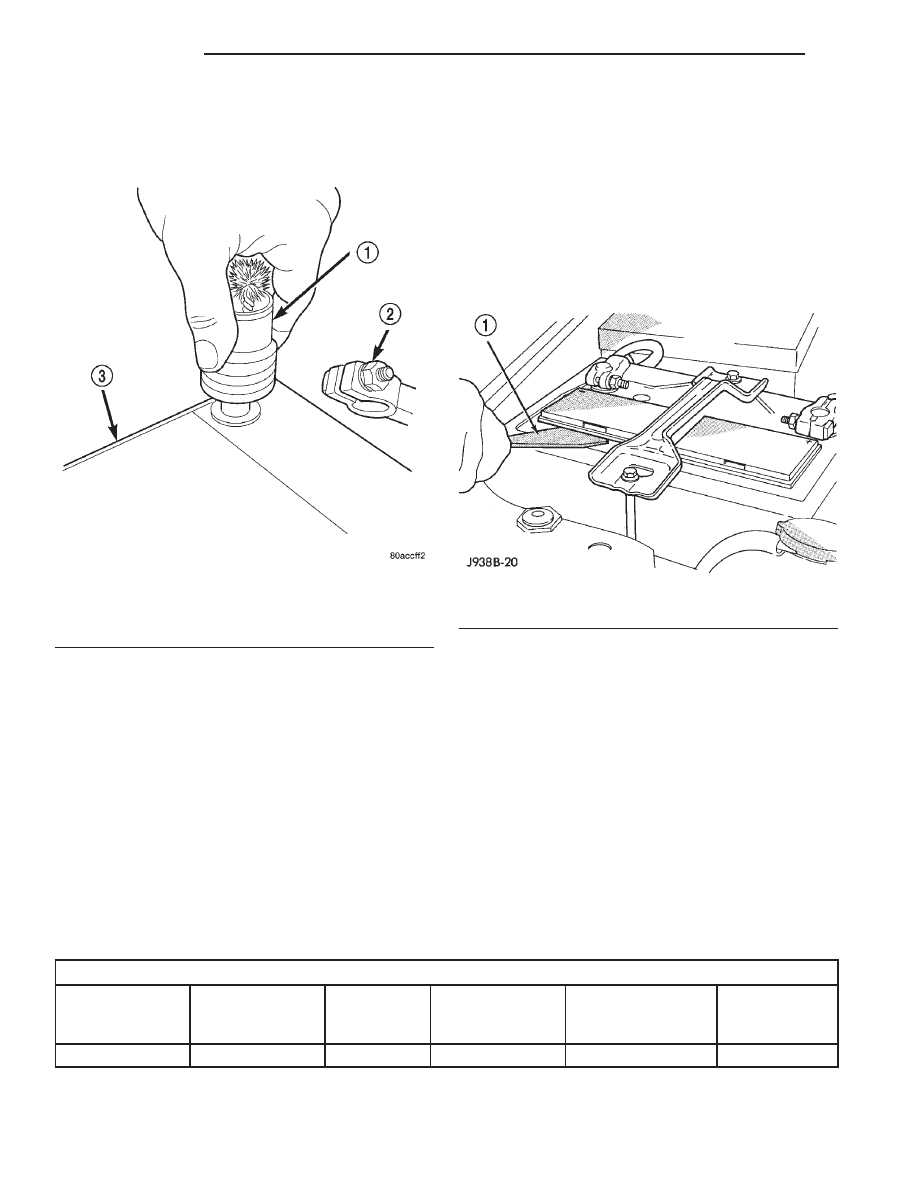
(5) Clean any corrosion from the battery terminal

posts with a wire brush or a post and terminal
cleaner, and a sodium bicarbonate (baking soda) and
warm water cleaning solution (Fig. 26).

INSPECTION

(1) Inspect the battery cable terminal clamps for

damage. Replace any battery cable that has a dam-
aged or deformed terminal clamp.

(2) Inspect the battery tray and battery hold down

hardware for damage. Replace any damaged parts.

(3) Slide the thermoguard off of the battery case.

Inspect the battery case for cracks or other damage
that could result in electrolyte leaks. Also, check the
battery terminal posts for looseness. Batteries with

damaged cases or loose terminal posts must be
replaced.

(4) Inspect the battery thermoguard for tears,

cracks, deformation or other damage. Replace any
battery thermoguard that has been damaged.

(5) Inspect the electrolyte level in the battery. Use

a putty knife or another suitable wide flat-bladed tool
to pry the cell caps off (Fig. 27). Do not use a screw-
driver. Add distilled water to each cell until the liq-
uid reaches the bottom of the vent well. DO NOT
OVERFILL.

(6) Inspect the battery built-in test indicator sight

glass for an indication of the battery condition. If the
battery is discharged, charge as required. Refer to
Battery in the index of this service manual for the
location of the proper battery diagnosis and testing
procedures for more information on the use of the
battery built-in test indicator. Also refer to Battery
Charging 
in the index of this service manual for the
location of the proper battery charging procedures.

SPECIFICATIONS

BATTERY

Battery Classifications and Ratings

Part Number

BCI Group Size

Classification

Cold

Cranking

Amperage

Reserve

Capacity

Ampere-Hours

Load Test

Amperage

56041105AB

34

500

110 Minutes

60

250

Fig. 26 Clean Battery Terminal Post - Typical

1 – TERMINAL BRUSH
2 – BATTERY CABLE
3 – BATTERY

Fig. 27 Removing Battery Cell Caps - Typical

1 – PUTTY KNIFE

8A - 24

BATTERY

XJ

CLEANING AND INSPECTION (Continued)

STARTING SYSTEMS

TABLE OF CONTENTS

page

page

DESCRIPTION AND OPERATION

STARTING SYSTEM . . . . . . . . . . . . . . . . . . . . . . . 1
STARTER MOTOR. . . . . . . . . . . . . . . . . . . . . . . . . 2
STARTER RELAY . . . . . . . . . . . . . . . . . . . . . . . . . 3

DIAGNOSIS AND TESTING

STARTING SYSTEM . . . . . . . . . . . . . . . . . . . . . . . 4
STARTER MOTOR NOISE - 2.5L ENGINE . . . . . . 8
STARTER MOTOR. . . . . . . . . . . . . . . . . . . . . . . . . 9

STARTER RELAY . . . . . . . . . . . . . . . . . . . . . . . . 10

REMOVAL AND INSTALLATION

STARTER MOTOR. . . . . . . . . . . . . . . . . . . . . . . . 11
STARTER RELAY . . . . . . . . . . . . . . . . . . . . . . . . 13

CLEANING AND INSPECTION

STARTING SYSTEM . . . . . . . . . . . . . . . . . . . . . . 14

SPECIFICATIONS

STARTING SYSTEM . . . . . . . . . . . . . . . . . . . . . . 15

DESCRIPTION AND OPERATION

STARTING SYSTEM

DESCRIPTION

An electrically operated engine starting system is

standard factory-installed equipment on this model.
The starting system is designed to provide the vehi-
cle operator with a convenient, efficient and reliable
means of cranking and starting the internal combus-
tion engine used to power the vehicle and all of its
accessory systems. The starting system includes the
following major components:

• Battery

• Battery cables

• Clutch pedal position switch (manual transmis-

sion)

• Ignition switch

• Park/neutral position switch (automatic trans-

mission)

• Starter motor (including the integral starter

solenoid)

• Starter relay.
The starting system consists of two separate cir-

cuits. A high-amperage feed circuit that feeds the
starter motor between 150 and 350 amperes of bat-
tery current, and a low-amperage control circuit that
operates on less than 20 amperes of battery current.
The starting system high-amperage feed circuit
includes the battery, the battery cables, the contact
disc portion of the starter solenoid, and the starter
motor. The following starting system feed circuit
components are covered in more detail in other areas
of this service manual:

• The battery is located in the passenger side

front corner of the engine compartment, near the
upper radiator crossmember and provides the electri-
cal current needed to operate the starting system.

Refer to Battery in the index of this service manual
for the location of more information on the battery.

• The battery cables connect the battery to the

electrical system of the vehicle and to the starting
system. Refer to Battery Cables in the index of this
service manual for the location of more information
on the battery cables.

The starting system low-amperage control circuit

includes the ignition switch, the clutch pedal position
switch (manual transmission), the park/neutral posi-
tion switch (automatic transmission), the starter
relay, the electromagnetic windings of the starter
solenoid, and the wire harnesses that connect these
components. The following starting system control
circuit components are covered in more detail in
other areas of this service manual:

• The ignition switch is mounted on the bottom of

the steering column and actuates the starting system
when a properly coded ignition key is inserted in the
ignition lock cylinder on the right side of the steering
column and turned to the spring-loaded momentary
Start position. Refer to Ignition Switch and Key
Lock Cylinder 
in the index of this service manual
for the location of more information on the ignition
switch.

• The clutch pedal position switch is integral to

the master cylinder of the clutch hydraulic linkage
assembly on models equipped with a manual trans-
mission. Refer to Clutch Hydraulic Linkage in the
index of this service manual for the location of more
information on the clutch pedal position switch.

• On models with the 2.5L engine, the park/neu-

tral position switch is threaded into the left side of
the automatic transmission case and has a spring-
loaded plunger that is actuated by a cam integral to
the gearshift mechanism within the transmission.
The back up lamp switch is also integral to the park/
neutral position switch. On models with the 4.0L

XJ

STARTING SYSTEMS

8B - 1

engine, the park/neutral position switch is mounted
on the right side of the automatic transmission case.
The switch is indexed to and driven by the transmis-
sion manual valve shaft. Refer to Park/Neutral
Position Switch 
in the index of this service manual
for the location of more information on either version
of the park/neutral position switch.

Following are general descriptions of the starter

relay and the starter motor. See the owner’s manual
in the vehicle glove box for more information on the
features, use and operation of the starting system.
Refer to Starting System in the index of this ser-
vice manual for the location of complete wiring dia-
grams for the starting system.

NOTE: This group covers both Left-Hand Drive
(LHD) and Right-Hand Drive (RHD) versions of this
model. Whenever required and feasible, the RHD
versions of affected vehicle components have been
constructed as mirror-image of the LHD versions.
While most of the illustrations used in this group
represent only the LHD version, the diagnostic and
service

procedures

outlined

can

generally

be

applied to either version. Exceptions to this rule
have been clearly identified as LHD or RHD, if a
special illustration or procedure is required.

OPERATION

If the vehicle is equipped with a manual transmis-

sion, the clutch pedal position switch is installed in
series between the ignition switch and the coil bat-
tery terminal of the starter relay. This normally open
switch prevents the starter relay from being ener-
gized when the ignition switch is turned to the
momentary Start position, unless the clutch pedal is
fully depressed. This feature prevents starter motor
operation while the clutch disc and the flywheel are
engaged. The starter relay coil ground terminal is
always grounded on vehicles with a manual trans-
mission.

If the vehicle is equipped with an automatic trans-

mission, battery voltage is supplied through the low-
amperage control circuit to the coil battery terminal
of the starter relay when the ignition switch is
turned to the momentary Start position. The park/
neutral position switch is installed in series between
the starter relay coil ground terminal and ground.
This normally open switch prevents the starter relay
from being energized and the starter motor from
operating unless the automatic transmission gear
selector is in the Neutral or Park positions.

When the starter relay coil windings are energized,

the relay directs battery current to the starter sole-
noid coil windings. When the starter solenoid coil
windings are energized, the solenoid directs battery
current to the starter motor, which cranks the engine

by engaging the starter pinion gear with the starter
ring gear. Once the engine starts, the ignition switch
key is released by the vehicle operator. When the
ignition switch key is released, the switch automati-
cally returns to the On position, which de-energizes
the starting system.

STARTER MOTOR

DESCRIPTION

The starter motors used for both the 2.5L and the

4.0L engines available in this model are not inter-
changeable (Fig. 1). However, each of these starter
motors incorporates several of the same features to
create a reliable, efficient, compact, lightweight and
powerful unit. Both starters feature high torque
direct current electric motors. Inside both starter
motors the commutator of the rotating motor arma-
ture is contacted by four brushes. The starter motor
for the 2.5L engine is driven by four permanent mag-
net field poles, while the starter motor for the 4.0L
engine is driven by four electromagnetic field coils
wound around four pole shoes. The 2.5L starter
motor is rated at 1.2 kilowatts (about 1.6 horse-
power) output at 12 volts, while the 4.0L starter
motor is rated at 1.4 kilowatts (about 1.9 horse-
power) output at 12 volts.

These starter motors are equipped with a plane-

tary gear reduction (intermediate transmission) sys-
tem. The planetary gear reduction system consists of
a gear that is integral to the output end of the elec-
tric motor armature shaft that is in continual
engagement with a larger gear that fits on a spline
on the input end of the starter pinion gear shaft.
This feature makes it possible to reduce the dimen-
sions of the starter. At the same time, it allows
higher

armature

rotational

speed

and

delivers

increased torque through the starter pinion gear.

Fig. 1 Starter Motors

1 – STARTER SOLENOID

8B - 2

STARTING SYSTEMS

XJ

DESCRIPTION AND OPERATION (Continued)

Both starter motors use an overrunning clutch and
starter pinion gear unit to engage and drive the
starter ring gear, which is integral to the flywheel
(manual transmission) or torque converter drive
plate (automatic transmission) mounted on the rear
crankshaft flange. Shims are available and can be
used to adjust the 2.5L starter motor mounting posi-
tion to correct for improper starter pinion gear to
starter ring gear engagement.

The starter motors for both engines are activated

by an integral heavy duty starter solenoid switch
mounted to the overrunning clutch housing. This
electromechanical switch connects and disconnects
the feed of battery current to the starter motor
through a movable contact on one end of the solenoid
core or plunger. At the same time, the solenoid
plunger actuates a shift fork that engages and disen-
gages the starter pinion gear with a starter ring
gear. The starter solenoid has two electromagnetic
windings or coils, a pull-in coil and a hold-in coil. The
pull-in coil requires more battery current and pro-
duces a stronger electromagnetic field than the
hold-in coil.

Both starter motors are serviced only as a unit

with their starter solenoids, and cannot be repaired.
If either component is faulty or damaged, the entire
starter motor and starter solenoid unit must be
replaced.

OPERATION

When the starter solenoid pull-in coil windings are

energized the solenoid plunger is drawn into the elec-
tromagnetic coil. The solenoid plunger pulls the shift
lever in the starter motor. This engages the starter
overrunning clutch and pinion gear with the starter
ring gear on the manual transmission flywheel or on
the automatic transmission torque converter drive
plate. As the solenoid plunger reaches the end of its
travel, it moves the solenoid contact disc to complete
the high-amperage starter feed circuit and energizes
the solenoid hold-in coil windings. Battery current
now flows between the solenoid battery terminal and
the starter field terminal, energizing the starter and
cranking the engine.

Once the engine starts, the overrunning clutch pro-

tects the starter motor from damage by allowing the
starter pinion gear to spin faster than the pinion
shaft. When the solenoid plunger hold-in coil is de-
energized, the solenoid plunger return spring returns
the plunger to its relaxed position. This causes the
solenoid contact disc to open the starter feed circuit,
and the shift lever to disengage the overrunning
clutch and pinion gear unit from the starter ring
gear.

STARTER RELAY

DESCRIPTION

The starter relay (Fig. 2) is an electromechanical

device that switches battery current to the pull-in
coil of the starter solenoid when the ignition switch
is turned to the Start position. The starter relay is
located in the Power Distribution Center (PDC), in
the engine compartment. See the fuse and relay lay-
out label affixed to the inside surface of the PDC
cover for starter relay identification and location.

The starter relay is a International Standards

Organization (ISO) relay. Relays conforming to the
ISO specifications have common physical dimensions,
current capacities, terminal patterns, and terminal
functions.

The starter relay cannot be repaired or adjusted

and, if faulty or damaged, it must be replaced.

OPERATION

The ISO relay consists of an electromagnetic coil, a

resistor or diode, and three (two fixed and one movable)
electrical contacts. The movable (common feed) relay
contact is held against one of the fixed contacts (nor-
mally closed) by spring pressure. When the electromag-
netic coil is energized, it draws the movable contact
away from the normally closed fixed contact, and holds
it against the other (normally open) fixed contact.

When the electromagnetic coil is de-energized,

spring pressure returns the movable contact to the
normally closed position. The resistor or diode is con-
nected in parallel with the electromagnetic coil in the
relay, and helps to dissipate voltage spikes that are
produced when the coil is de-energized.

TERMINAL LEGEND

NUMBER

IDENTIFICATION

30

COMMON FEED

85

COIL GROUND

86

COIL BATTERY

87

NORMALLY OPEN

87A

NORMALLY CLOSED

Fig. 2 Starter Relay

XJ

STARTING SYSTEMS

8B - 3

DESCRIPTION AND OPERATION (Continued)


Content   ..  84  85  86  87   ..