Jeep XJ. Manual - part 74


  Index      Jeep     Jeep XJ - service repair manual 2001 year


Search            


Content   ..  72  73  74  75   ..


Jeep XJ. Manual - part 74


on the front of the coolant tank (Fig. 4). For informa-
tion, refer to Group 8E, Instrument Panel and
Gauges.

If this lamp is illuminated, it indicates the need for

service.

THERMOSTAT

DESCRIPTION

A pellet-type thermostat controls the operating

temperature of the engine by controlling the amount
of coolant flow to the radiator.

OPERATION

The thermostat starts to open at 80°C (176°F).

Above this temperature, coolant is allowed to flow to

the radiator. This provides quicker engine warmup
and overall temperature control.

The same thermostat is used for winter and sum-

mer seasons. An engine should not be operated with-
out a thermostat, except for servicing or testing.
Operating without a thermostat causes other prob-
lems. These are: longer engine warmup time, unreli-
able

warmup

performance,

increased

exhaust

emissions and crankcase condensation. This conden-
sation can result in sludge formation.

CAUTION: Do not operate an engine without a ther-
mostat, except for servicing or testing.

PRESSURE/VENT CAP

DESCRIPTION

The pressure/vent cap is threaded-on to the coolant

tank. This cap releases excess pressure at some point
within a range of 90-117 kPa (13- 17 psi). The actual
pressure relief point (in pounds) is labeled on top of
the cap (Fig. 5).

OPERATION

The cooling system will operate at pressures up to

103 kPa (15 psi). This results in a higher coolant
boiling point allowing increased radiator cooling
capacity. The cap (Fig. 5) contains a spring-loaded
pressure relief valve. This valve opens when system
pressure reaches approximately 103 kPa (15 psi).

When the engine is cooling down, vacuum is

formed within the cooling system. To prevent collapse
of the radiator and coolant hoses from this vacuum, a
vacuum valve is used within the cap. This valve pre-
vents excessive pressure differences from occurring

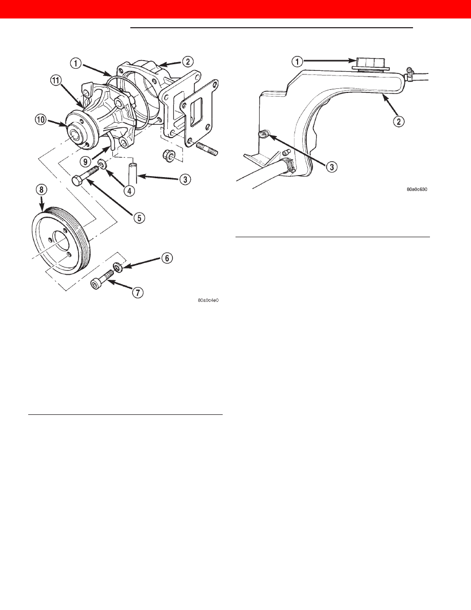
Fig. 3 Water Pump— Typical

1 – O-RING SEAL
2 – WATER PUMP ADAPTER
3 – DRAIN HOSE
4 – WASHER
5 – PUMP MOUNTING BOLTS (4)
6 – WASHER
7 – WATER PUMP PULLEY BOLTS (3)
8 – WATER PUMP PULLEY
9 – VENT TUBE
10 – PUMP HUB
11 – WATER PUMP

Fig. 4 Low Coolant Level Sensor

1 – PRESSURE/VENT CAP
2 – PRESSURIZED COOLANT TANK
3 – LOW COOLANT LEVEL SENSOR

7 - 4

COOLING SYSTEM

XJ

DESCRIPTION AND OPERATION (Continued)

2000 JEEP CHEROKEE

between the closed cooling system and the atmo-
sphere. If the vacuum valve is stuck shut, the radia-
tor and/or cooling system hoses will collapse on cool-
down.

NOTE: Do not use any type of tool when tightening
the cap. Hand tighten only.

COOLANT PERFORMANCE

DESCRIPTION

The required ethylene-glycol (antifreeze) and water

mixture depends upon the climate and vehicle oper-
ating conditions. The recommended mixture of 50/50
ethylene-glycol and water will provide protection
against freezing to -37 deg. C (-35 deg. F). The anti-
freeze concentration must always be a minimum of
44 percent, year-round in all climates. If percentage
is lower than 44 percent, engine parts may be
eroded by cavitation, and cooling system com-

ponents may be severely damaged by corrosion.
Maximum protection against freezing is provided
with a 68 percent antifreeze concentration, which
prevents freezing down to -67.7 deg. C (-90 deg. F). A
higher percentage will freeze at a warmer tempera-
ture. Also, a higher percentage of antifreeze can
cause the engine to overheat because the specific
heat of antifreeze is lower than that of water.

100 Percent Ethylene-Glycol—Should Not Be Used in
DaimlerChrysler Corporation Vehicles

Use of 100 percent ethylene-glycol will cause for-

mation of additive deposits in the system, as the cor-
rosion inhibitive additives in ethylene-glycol require
the presence of water to dissolve. The deposits act as
insulation, causing temperatures to rise to as high as
149 deg. C (300) deg. F). This temperature is hot
enough to melt plastic and soften solder. The
increased temperature can result in engine detona-
tion. In addition, 100 percent ethylene-glycol freezes
at 22 deg. C (-8 deg. F ).

Propylene-glycol Formulations—Should Not Be Used in
DaimlerChrysler Corporation Vehicles

Propylene-glycol formulations do not meet

Chrysler coolant specifications. It’s overall effec-
tive temperature range is smaller than that of ethyl-
ene-glycol. The freeze point of 50/50 propylene-glycol
and water is -32 deg. C (-26 deg. F). 5 deg. C higher
than ethylene-glycol’s freeze point. The boiling point
(protection against summer boil-over) of propylene-
glycol is 125 deg. C (257 deg. F ) at 96.5 kPa (14 psi),
compared to 128 deg. C (263 deg. F) for ethylene-gly-
col. Use of propylene-glycol can result in boil-over or
freeze-up in Chrysler vehicles, which are designed for
ethylene-glycol. Propylene glycol also has poorer heat
transfer characteristics than ethylene glycol. This
can increase cylinder head temperatures under cer-
tain conditions.

Propylene-glycol/Ethylene-glycol Mixtures—Should Not Be
Used in DaimlerChrysler Corporation Vehicles

Propylene-glycol/ethylene-glycol

Mixtures

can

cause the destabilization of various corrosion inhibi-
tors, causing damage to the various cooling system
components. Also, once ethylene-glycol and propy-
lene-glycol based coolants are mixed in the vehicle,
conventional methods of determining freeze point will
not be accurate. Both the refractive index and spe-
cific gravity differ between ethylene glycol and propy-
lene glycol.

COOLING SYSTEM HOSES

DESCRIPTION

Rubber hoses route coolant to and from the radia-

tor, and heater core.

Fig. 5 Coolant Tank Pressure/Vent Cap

1 – RELEASE PRESSURE
2 – CAP COVER
3 – SPRING
4 – GASKET
5 – RUBBER VACUUM VALVE
6 – PRESSURE VALVE

XJ

COOLING SYSTEM

7 - 5

DESCRIPTION AND OPERATION (Continued)

2000 JEEP CHEROKEE

The radiator lower hose is spring-reinforced to pre-

vent collapse from water pump suction at high
engine speeds.

WARNING: CONSTANT TENSION HOSE CLAMPS
ARE USED ON MOST COOLING SYSTEM HOSES.
WHEN REMOVING OR INSTALLING, USE ONLY
TOOLS DESIGNED FOR SERVICING THIS TYPE OF
CLAMP (Fig. 6). ALWAYS WEAR SAFETY GLASSES
WHEN SERVICING CONSTANT TENSION CLAMPS.

CAUTION: A number or letter is stamped into the
tongue of constant tension clamps (Fig. 7). If
replacement is necessary, use only an original
equipment clamp with matching number or letter.

Inspect the hoses at regular intervals. Replace

hoses that are cracked, feel brittle when squeezed, or
swell excessively when the system is pressurized.

For all vehicles: Be sure that hoses are positioned

with

sufficient

clearance.

Check

clearance

from

exhaust manifolds and pipe, fan blades, drive belts
and sway bars. Improperly positioned hoses can be
damaged, resulting in coolant loss and engine over-
heating.

Ordinary worm gear type hose clamps (when

equipped) can be removed with a straight screw-
driver or a hex socket. To prevent damage to
hoses or clamps, the hose clamps should be
tightened to 4 N·m (34 in. lbs.) torque. Do not
over tighten hose clamps.

When performing a hose inspection, inspect the

radiator lower hose for proper position and condition
of the internal spring.

VISCOUS FAN DRIVE

DESCRIPTION

The thermal viscous fan drive (Fig. 8) is a silicone-

fluid-filled coupling. It connects the fan blade assem-
bly to the fan pulley.

OPERATION

The coupling allows the fan to be driven in a nor-

mal manner. This is done at low engine speeds while
limiting the top speed of the fan to a predetermined
maximum level at higher engine speeds. A bimetallic

Fig. 6 Hose Clamp Tool

1 – HOSE CLAMP TOOL 6094
2 – HOSE CLAMP

Fig. 7 Clamp Number/Letter Location

1 – TYPICAL CONSTANT TENSION HOSE CLAMP
2 – CLAMP NUMBER/LETTER LOCATION
3 – TYPICAL HOSE

Fig. 8 Viscous Fan Drive

1 – MOUNTING NUT TO FAN PULLEY SHAFT
2 – THERMOSTATIC SPRING
3 – VISCOUS FAN DRIVE

7 - 6

COOLING SYSTEM

XJ

DESCRIPTION AND OPERATION (Continued)

2000 JEEP CHEROKEE

coil spring is located on the front face. This spring
coil reacts to the temperature of the radiator dis-
charge air. It engages the viscous fan drive for higher
fan speed if the air temperature from the radiator
rises above a certain point. Until additional engine
cooling is necessary, the fan will remain at a reduced
rpm regardless of engine speed.

The viscous fan drive will only engage when suffi-

cient heat is present. This is when the air flowing
through the radiator core causes a reaction from the
bimetallic coil. It then increases fan speed to provide
the necessary additional engine cooling.

Once the engine has cooled, the radiator discharge

temperature will drop. The bimetallic coil again
reacts and the fan speed is reduced to the previous
disengaged speed.

CAUTION: Some engines equipped with serpentine
drive belts have reverse rotating fans and viscous
fan

drives.

They

are

marked

with

the

word

REVERSE to designate their usage. Installation of
the wrong fan or viscous fan drive can result in
engine overheating.

NOISE

NOTE: It is normal for fan noise to be louder (roar-
ing) when:

• The underhood temperature is above the engage-

ment point for the viscous drive coupling. This may
occur when ambient (outside air temperature) is very
high.

• Engine loads and temperatures are high such as

when towing a trailer.

• Cool silicone fluid within the fan drive unit is

being redistributed back to its normal disengaged
(warm) position. This can occur during the first 15
seconds to one minute after engine start-up on a cold
engine.

LEAKS

Viscous fan drive operation is not affected by small

oil stains near the drive bearing. If leakage appears
excessive, replace the fan drive unit.

BELT TENSION

DESCRIPTION

Correct accessory drive belt tension is required to

be sure of optimum performance of belt driven engine
accessories. If specified tension is not maintained,
belt slippage may cause; engine overheating, lack of
power steering assist, loss of air conditioning capac-
ity,

reduced

generator

output

rate

and

greatly

reduced belt life.

An automatic belt tensioner is used to maintain

correct belt tension at all times. Do not attempt to
check belt tension with a belt tension gauge on vehi-
cles equipped with an automatic belt tensioner.

AUTOMATIC BELT TENSIONER

DESCRIPTION

Drive belt tension is controlled by a spring loaded

automatic belt tensioner located below and to the
front of the engine oil filter (Fig. 9).

WARNING: BECAUSE

OF

HIGH

SPRING

PRES-

SURE, DO NOT ATTEMPT TO DISASSEMBLE THE
AUTOMATIC BELT TENSIONER. UNIT IS SERVICED
AS AN ASSEMBLY.

Fig. 9 Automatic Belt Tensioner Assembly

1 – FAN PULLEY
2 – IDLER PULLEY
3 – IDLER PULLEY
4 – GENERATOR
5 – POWER STEERING PUMP
6 – DRIVE BELT
7 – CRANKSHAFT PULLEY
8 – AUTOMATIC BELT TENSIONER

XJ

COOLING SYSTEM

7 - 7

DESCRIPTION AND OPERATION (Continued)

2000 JEEP CHEROKEE


Content   ..  72  73  74  75   ..