Jeep XJ. Manual - part 63


  Index      Jeep     Jeep XJ - service repair manual 2001 year


Search            


Content   ..  61  62  63  64   ..


Jeep XJ. Manual - part 63


SPECIFICATIONS

SPECIFICATIONS

DESCRIPTION

TORQUE

Clutch Cover to Flywheel

Bolts . . . . . . . . . . . . . . . . . . . 50 N·m (37 ft. lbs.)

Clutch Housing to Transmission

Bolts . . . . . . . . . . . . . . . . . . . 46 N·m (34 ft. lbs.)

Flywheel to Crankshaft
Bolts . . . . . See removal and installation procedure.
Pilot Bearing Retainer to Flywheel/Crankshaft

Bolts . . . . . . . . . . . . . . . . . . . 28 N·m (20 ft. lbs.)

Clutch Housing to Engine

Top (2) Bolts . . . . . . . . . . . . . . 37 N·m (27 ft. lbs.)
Middle (2) Bolts . . . . . . . . . . . 58 N·m (43 ft. lbs.)
Bottom (2) Bolts . . . . . . . . . . . 75 N·m (55 ft. lbs.)

SPECIAL TOOLS

SPECIAL TOOLS

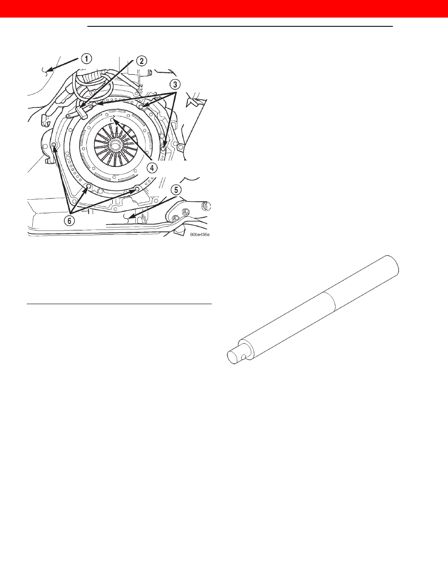
Fig. 18 Clutch Cover (Pressure Plate) View

1 – VEHICLE UNDERBODY
2 – ENGINE SPEED SENSOR
3 – PRESSURE PLATE RETAINING BOLTS
4 – CLUTCH COVER (PRESSURE PLATE)
5 – ENGINE OIL PAN
6 – PRESSURE PLATE RETAINING BOLTS

Universal Handle—C-4171

6 - 8

CLUTCH

XJ

REMOVAL AND INSTALLATION (Continued)

2000 JEEP CHEROKEE

COOLING SYSTEM

TABLE OF CONTENTS

page

page

DESCRIPTION AND OPERATION

COOLING SYSTEM . . . . . . . . . . . . . . . . . . . . . . . . 1
AUTOMATIC TRANSMISSION OIL COOLER. . . . . 2
COOLANT RESERVE/OVERFLOW SYSTEM . . . . . 2
COOLING SYSTEM FANS . . . . . . . . . . . . . . . . . . . 3
BLOCK HEATER . . . . . . . . . . . . . . . . . . . . . . . . . . 4
THERMOSTAT . . . . . . . . . . . . . . . . . . . . . . . . . . . . 4
RADIATOR . . . . . . . . . . . . . . . . . . . . . . . . . . . . . . 5
RADIATOR PRESSURE CAP . . . . . . . . . . . . . . . . . 5
WATER PUMP . . . . . . . . . . . . . . . . . . . . . . . . . . . 6
HOSE CLAMPS . . . . . . . . . . . . . . . . . . . . . . . . . . . 6
VISCOUS FAN DRIVE . . . . . . . . . . . . . . . . . . . . . . 7
ELECTRIC COOLING FAN . . . . . . . . . . . . . . . . . . . 8

DIAGNOSIS AND TESTING

ON-BOARD DIAGNOSTICS (OBD) . . . . . . . . . . . . 9
DRB SCAN TOOL . . . . . . . . . . . . . . . . . . . . . . . . . 9
ACCESSORY DRIVE BELT DIAGNOSIS. . . . . . . . . 9
PRELIMINARY CHECKS . . . . . . . . . . . . . . . . . . . 11
RADIATOR COOLANT FLOW CHECK . . . . . . . . . 17
COOLING SYSTEM—TESTING FOR LEAKS . . . . 17
VISCOUS FAN DRIVE . . . . . . . . . . . . . . . . . . . . . 19
ELECTRIC COOLING FAN . . . . . . . . . . . . . . . . . . 19
RADIATOR CAP-TO-FILLER NECK

SEAL—PRESSURE RELIEF CHECK . . . . . . . . . 20

RADIATOR CAP—PRESSURE TESTING. . . . . . . 20
COOLANT—LOW LEVEL AERATION . . . . . . . . . 21
DEAERATION . . . . . . . . . . . . . . . . . . . . . . . . . . . 21

SERVICE PROCEDURES

COOLANT—ROUTINE LEVEL CHECK. . . . . . . . . 21
COOLANT—ADDING ADDITIONAL. . . . . . . . . . . 21

COOLANT—LEVEL CHECK . . . . . . . . . . . . . . . . . 21
COOLING SYSTEM—DRAINING AND

FILLING . . . . . . . . . . . . . . . . . . . . . . . . . . . . . . 21

COOLING SYSTEM—REVERSE FLUSHING . . . . 22

REMOVAL AND INSTALLATION

TRANSMISSION OIL COOLERS . . . . . . . . . . . . . 23
COOLANT RESERVE TANK . . . . . . . . . . . . . . . . . 23
WATER PUMP . . . . . . . . . . . . . . . . . . . . . . . . . . 24
THERMOSTAT . . . . . . . . . . . . . . . . . . . . . . . . . . . 28
RADIATOR—2.5L . . . . . . . . . . . . . . . . . . . . . . . . 29
RADIATOR—4.0L . . . . . . . . . . . . . . . . . . . . . . . . 31
ELECTRIC COOLING FAN—2.5L . . . . . . . . . . . . 33
ELECTRIC COOLING FAN—4.0L . . . . . . . . . . . . 34
BLOCK HEATER . . . . . . . . . . . . . . . . . . . . . . . . . 35
ENGINE ACCESSORY DRIVE BELTS. . . . . . . . . . 35
COOLING SYSTEM FANS . . . . . . . . . . . . . . . . . . 38
VISCOUS FAN DRIVE REMOVAL/

INSTALLATION. . . . . . . . . . . . . . . . . . . . . . . . . 39

CLEANING AND INSPECTION

RADIATOR PRESSURE CAP . . . . . . . . . . . . . . . . 39
RADIATOR . . . . . . . . . . . . . . . . . . . . . . . . . . . . . 39
WATER PUMP . . . . . . . . . . . . . . . . . . . . . . . . . . 39
FAN BLADE . . . . . . . . . . . . . . . . . . . . . . . . . . . . . 39
COOLING SYSTEM HOSES. . . . . . . . . . . . . . . . . 40

SPECIFICATIONS

BELT TENSION . . . . . . . . . . . . . . . . . . . . . . . . . . 40
TORQUE SPECIFICATIONS . . . . . . . . . . . . . . . . . 40

SPECIAL TOOLS

COOLING . . . . . . . . . . . . . . . . . . . . . . . . . . . . . . 40

DESCRIPTION AND OPERATION

COOLING SYSTEM

DESCRIPTION

The cooling system regulates engine operating tem-

perature. It allows the engine to reach normal oper-
ating temperature as quickly as possible, maintains
normal operating temperature and prevents over-
heating.

The cooling system also provides a means of heat-

ing the passenger compartment and cooling the auto-

matic transmission fluid (if equipped). The cooling
system is pressurized and uses a centrifugal water
pump to circulate coolant throughout the system.

An optional factory installed heavy duty cooling

package is available on most models. The package
consists of a radiator that has an increased number
of cooling fins. Vehicles equipped with a 2.5L/4.0L
engine and heavy duty cooling and/or air condition-
ing also have an auxiliary electric cooling fan.

The cooling system consists of:
• A radiator

• Cooling fan (mechanical and/or electrical)

• Thermal viscous fan drive

XJ

COOLING SYSTEM

7 - 1

• Fan shroud

• Radiator pressure cap

• Thermostat

• Coolant reserve/overflow system

• Transmission oil cooler (if equipped with an

automatic transmission)

• Coolant

• Water pump

• Hoses and hose clamps
Cooling system circulation for 2.5L/4.0L models is

shown in (Fig. 1).

AUTOMATIC TRANSMISSION OIL COOLER

DESCRIPTION

All models equipped with an automatic transmis-

sion are equipped with a transmission oil cooler
mounted internally within the radiator tank. This
internal cooler is supplied as standard equipment on
all models equipped with an automatic transmission.

Transmission oil is cooled when it passes through

this separate cooler. In case of a leak in the internal
radiator mounted transmission oil cooler, engine cool-
ant may become mixed with transmission fluid or
transmission fluid may enter engine cooling system.
Both cooling system and transmission should be
drained

and

inspected

if

the

internal

radiator

mounted transmission cooler is leaking.

An auxiliary air-to-oil transmission oil cooler is

available with most engine packages.

The auxiliary air-to-oil transmission oil cooler is

located in front of the radiator or A/C condenser (if
equipped) and behind the grill. It is mounted to the
front frame crossmember.

The auxiliary oil coolers on all models operate in

conjunction with the internal radiator mounted main
oil cooler. The transmission oil is routed through the
main cooler first, then the auxiliary cooler, before
returning to the transmission.

COOLANT RESERVE/OVERFLOW SYSTEM

DESCRIPTION

The system works along with the radiator pressure

cap. This is done by using thermal expansion and
contraction of the coolant to keep the coolant free of
trapped air. It provides:

• A volume for coolant expansion and contraction.

• A convenient and safe method for checking/ad-

justing coolant level at atmospheric pressure. This is
done without removing the radiator pressure cap.

• Some reserve coolant to the radiator to cover

minor leaks and evaporation or boiling losses.

Fig. 1 Coolant Circulation—2.5L/4.0L Engines

1 – HEATER CORE
2 – TO COOLANT RESERVE/OVERFLOW TANK
3 – THERMOSTAT HOUSING
4 – RADIATOR
5 – WATER PUMP

Fig. 2 Auxiliary Transmission Oil Cooler

1 – AUXILIARY TRANSMISSION OIL COOLER

7 - 2

COOLING SYSTEM

XJ

DESCRIPTION AND OPERATION (Continued)

The coolant reserve/overflow system consists of a

radiator mounted pressurized cap, a plastic reserve/
overflow tank (Fig. 3) (Fig. 4), a tube (hose) connect-
ing the radiator and tank, and an overflow tube on
the side of the tank.

OPERATION

As the engine cools, a vacuum is formed in the

cooling system of both the radiator and engine. Cool-
ant will then be drawn from the coolant tank and
returned to a proper level in the radiator.

COOLING SYSTEM FANS

DESCRIPTION

All models are equipped with a viscous fan. This

thermal viscous fan drive is a torque-and-tempera-
ture-sensitive clutch unit. It automatically increases
or decreases fan speed to provide proper engine cool-
ing. Vehicles with a 2.5L/4.0L engine with air condi-
tioning, or 4.0L with “max” cooling also have an
auxiliary electrical cooling fan.

Fig. 3 Reserve/Overflow Tank—Except Right Hand

Drive

1 – COOLANT RESERVE/OVERFLOW TANK
2 – CLAMP
3 – MOUNTING BOLTS
4 – TUBE TO RADIATOR

Fig. 4 Reserve/Overflow Tank—With Right Hand

Drive

1 – CLAMP
2 – COOLANT RESERVE/OVERFLOW TANK
3 – MOUNTING BOLTS
4 – LOWER BRACKET
5 – TUBE TO RADIATOR

Fig. 5 Viscous Fan Drive and Fan Blade Assembly

1 – VISCOUS FAN DRIVE
2 – FAN BLADE ASSEMBLY

XJ

COOLING SYSTEM

7 - 3

DESCRIPTION AND OPERATION (Continued)


Content   ..  61  62  63  64   ..