Jeep XJ. Manual - part 51


  Index      Jeep     Jeep XJ - service repair manual 2001 year


Search            


Content   ..  49  50  51  52   ..


Jeep XJ. Manual - part 51


CAUTION: Verify brake hose is not twisted or
kinked before tightening fitting bolt.

(5) Bleed base brake system.
(6) Install wheel and tire assemblies.
(7) Remove supports and lower vehicle.
(8) Verify firm pedal before moving vehicle.

FRONT DISC BRAKE SHOES

REMOVAL

(1) Raise and support vehicle.
(2) Remove wheel and tire assembly.
(3) Remove caliper.
(4) Pressing one end of outboard shoe inward to

disengage shoe lug. Then rotate shoe upward until
retainer spring clears caliper. Press opposite end of
shoe inward to disengage shoe lug and rotate shoe up
and out of caliper (Fig. 31).

(5) Grasp ends of inboard shoe and tilt shoe out-

ward to release springs from caliper piston (Fig. 32)
and remove shoe from caliper.

NOTE: If original brake shoes will be used, keep
them in sets left and right. They are not inter-
changeable.

(6) Secure caliper to nearby suspension part with

wire. Do not allow brake hose to support caliper
weight.

(7) Wipe caliper off with shop rags or towels.

CAUTION: Do not use compressed air, this can
unseat dust boot and force dirt into piston bore.

INSTALLATION

(1) Install inboard shoe in caliper and verify shoe

retaining is fully seated into the piston.

(2) Starting one end of outboard shoe in caliper

and rotating shoe downward into place. Verify shoe
locating lugs and shoe spring are seated.

(3) Install caliper.
(4) Install wheel and tire assembly.
(5) Remove support and lower vehicle.
(6) Pump brake pedal until caliper pistons and

brake shoes are seated.

(7) Top off brake fluid level if necessary.

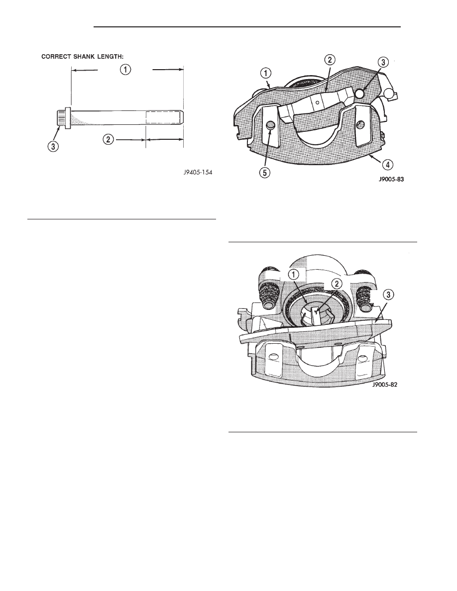
Fig. 30 Mounting Bolt Dimensions

1 – 67 mm (

6

0.6 mm) 2.637 in. (

6

0.0236 in.)

2 – 22 mm (0.866 in.) THREAD LENGTH
3 – CALIPER BOLT

Fig. 31 Outboard Brake Shoe Removal

1 – OUTBOARD BRAKESHOE
2 – SHOE SPRING
3 – LOCATING LUG
4 – CALIPER
5 – LOCATING LUG

Fig. 32 Inboard Brake Shoe Removal

1 – CALIPER PISTON
2 – SHOE SPRINGS
3 – INBOARD BRAKESHOE

5 - 20

BRAKES

XJ

REMOVAL AND INSTALLATION (Continued)

DISC BRAKE ROTOR

REMOVAL

(1) Remove wheel and tire assemble.
(2) Remove caliper.
(3) Remove retainers securing rotor to hub studs

(Fig. 33).

(4) Remove rotor from hub.
(5) If rotor shield requires service, remove front

hub and bearing assembly.

INSTALLATION

(1) If new rotor is being installed, remove protec-

tive coating from rotor surfaces with carburetor
cleaner.

(2) Install rotor on hub.
(3) Install caliper.
(4) Install wheel and tire assembly.

DRUM BRAKE SHOES

REMOVAL

(1) Raise vehicle and remove rear wheels.
(2) Remove

and

discard

spring

nuts

securing

drums to wheel studs.

(3) Remove brake drums. If drums prove difficult

to remove, retract brake shoes. Remove access plug
at the rear of backing plate and back off adjuster
screw with brake tool and screwdriver.

(4) Remove U-clip and washer securing adjuster

cable to parking brake lever (Fig. 34).

(5) Remove primary and secondary return springs

from anchor pin with brake spring pliers.

(6) Remove hold-down springs, retainers and pins

with standard retaining spring tool.

(7) Install spring clamps on wheel cylinders to

hold pistons in place.

(8) Remove adjuster lever, adjuster screw and

spring.

(9) Remove adjuster cable and cable guide.
(10) Remove brake shoes and parking brake strut.
(11) Disconnect cable from parking brake lever and

remove lever.

INSTALLATION

(1) Clean support plate with brake cleaner.
(2) If new drums are being installed, remove pro-

tective coating with carburetor cleaner followed by
final rinse with brake cleaner.

(3) Clean and lubricate anchor pin with light coat

of Mopar multi-mileage grease.

(4) Apply Mopar multi-mileage grease to brake

shoe contact surfaces of support plate (Fig. 35).

(5) Lubricate adjuster screw threads and pivot

with spray lube.

(6) Attach parking brake lever to secondary brake

shoe. Use new washer and U-clip to secure lever.

(7) Remove wheel cylinder clamps.
(8) Attach parking brake cable to lever.
(9) Install brake shoes on support plate. Secure

shoes with new hold-down springs, pins and retain-
ers.

(10) Install parking brake strut and spring.
(11) Install guide plate and adjuster cable on

anchor pin.

(12) Install primary and secondary return springs.
(13) Install adjuster cable guide on secondary

shoe.

(14) Lubricate and assemble adjuster screw.
(15) Install adjuster screw, spring and lever and

connect to adjuster cable.

(16) Adjust shoes to drum.
(17) Install wheel/tire assemblies and lower vehi-

cle.

(18) Verify firm brake pedal before moving vehicle.

WHEEL CYLINDER

REMOVAL

(1) Remove wheel and tire assembly.
(2) Remove brake drum.
(3) Disconnect wheel cylinder brake line.
(4) Remove brake shoe return springs and move

shoes out of engagement with cylinder push rods.

(5) Remove cylinder attaching bolts and remove

cylinder from support plate.

Fig. 33 Rotor & Hub

1 – ROTOR
2 – RETAINER
3 – BEARING NUT
4 – NUT LOCK
5 – COTTER PIN
6 – WASHER

XJ

BRAKES

5 - 21

REMOVAL AND INSTALLATION (Continued)

INSTALLATION

(1) Apply bead of silicone sealer around cylinder

mounting surface of support plate.

(2) Install cylinder mounting bolts and tighten to

20 N·m (15 ft. lbs.).

(3) Connect brake line to cylinder.
(4) Install brake shoe return spring.
(5) Install brake drum.
(6) Install wheel and tire assembly.
(7) Bleed base brake system.

BRAKE SUPPORT PLATE

REMOVAL

(1) Remove wheel and tire assembly and brake

drum.

(2) Remove brake shoe assembly.
(3) Remove parking brake cable from parking

brake lever.

(4) Compress parking brake cable retainer tabs.

Then push retainer and cable through and out of
support plate.

Fig. 34 Drum Brake Components—Typical

1 – ADJUSTER LEVER
2 – ADJUSTER CABLE
3 – HOLDDOWN SPRING AND RETAINERS
4 – ADJUSTER LEVER SPRING
5 – TRAILING SHOE
6 – CYLINDER-TO-SUPPORT SEAL
7 – HOLDDOWN PINS
8 – ACCESS PLUGS
9 – SUPPORT PLATE
10 – CABLE HOLE PLUG

11 – PARK BRAKE STRUT AND SPRING
12 – ADJUSTER SCREW ASSEMBLY
13 – HOLDDOWN SPRING AND RETAINERS
14 – LEADING SHOE
15 – CABLE GUIDE
16 – SHOE RETURN SPRINGS
17 – SHOE GUIDE PLATE
18 – PIN
19 – SHOE SPRING
20 – PARK BRAKE LEVER

Fig. 35 Shoe Contact Surfaces

1 – ANCHOR PIN
2 – SUPPORT PLATE
3 – SHOE CONTACT SURFACES

5 - 22

BRAKES

XJ

REMOVAL AND INSTALLATION (Continued)

(5) Disconnect brake line at wheel cylinder.
(6) Remove wheel cylinder from support plate.
(7) Remove axle shaft, refer to Group 3 for proce-

dures.

(8) Remove bolts attaching support plate to axle

and remove support plate.

INSTALLATION

(1) Apply bead of silicone sealer around axle

mounting surface of support plate.

(2) Install support plate on axle flange. Tighten

attaching bolts to 115 N·m (85 ft. lbs.).

(3) Apply bead of silicone sealer around wheel cyl-

inder mounting surface and install wheel cylinder.

(4) Install brake line in wheel cylinder.
(5) Install parking brake cable in support plate.
(6) Install axle shaft, refer to Group 3 for proce-

dure.

(7) Connect parking brake cable to lever on sec-

ondary shoe and install brake shoes on support plate.

(8) Adjust brake shoes to drum with brake gauge.
(9) Install brake drum and wheel and tire assem-

bly.

(10) Bleed brake system.

REAR PARKING BRAKE CABLES

REMOVAL

(1) Raise vehicle and loosen equalizer nuts until

rear cables are slack.

(2) Disengage cables from equalizer and compress

cable retainers with a worm drive hose clamp.

(3) Remove cables from the cable bracket (Fig. 36).
(4) Remove rear wheel and brake drums.
(5) Remove secondary brake shoe and disconnect

cable from lever on brake shoe.

(6) Compress cables retainer with worm drive hose

clamp (Fig. 37) and remove cables from backing
plates.

INSTALLATION

(1) Install new cables in backing plates. Be sure

cable retainer is seated.

(2) Attach cable to lever on brake shoe and install

brake shoe on backing plate.

(3) Adjust brake shoes to drum with brake gauge.
(4) Install brake drums and wheels.
(5) Install cables into the cable bracket and insure

retainers are seated in the bracket.

(6) Engage the cable ends into the equalizer and

install equalizer nut.

(7) Adjust parking brakes.

PARKING BRAKE LEVER

The center console must be removed to service the

parking brake lever. Refer to Group 23 Interior Com-
ponents for service procedures.

Fig. 36 Parking Brake Cables

1 – REAR CABLES
2 – EQUALIZER
3 – FRONT CABLE
4 – TENSIONER ROD

Fig. 37 Cable Retainer

1 – CABLE RETAINER
2 – REAR CABLE
3 – WORM DRIVE HOSE CLAMP

XJ

BRAKES

5 - 23

REMOVAL AND INSTALLATION (Continued)


Content   ..  49  50  51  52   ..