Jeep XJ. Manual - part 23


  Index      Jeep     Jeep XJ - service repair manual 2001 year


Search            


Content   ..  21  22  23  24   ..


Jeep XJ. Manual - part 23


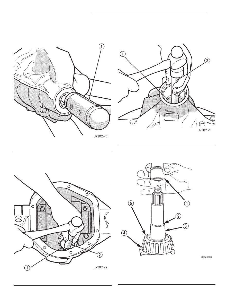
(6) Remove the pinion and collapsible spacer from

housing (Fig. 52). Catch the pinion with your hand to
prevent it from falling and being damaged.

(7) Remove the front pinion bearing cup, bearing,

oil slinger, if equipped, and pinion seal with Remover
C-4345 and Handle C–4171 (Fig. 53).

(8) Remove the rear pinion bearing cup from axle

housing (Fig. 54). Use Remover D-149 and Handle
C–4171.

(9) Remove the collapsible preload spacer from

pinion gear (Fig. 55).

Fig. 52 Remove Pinion

1 – RAWHIDE HAMMER

Fig. 53 Front Bearing Cup Removal

1 – REMOVER
2 – HANDLE

Fig. 54 Rear Bearing Cup Removal

1 – DRIVER
2 – HANDLE

Fig. 55 Collapsible Spacer

1 – COLLAPSIBLE SPACER
2 – SHOULDER
3 – PINION
4 – PINION DEPTH SHIM
5 – REAR BEARING

3 - 42

TUBE, 181, AND 186 FBI AXLE

XJ

REMOVAL AND INSTALLATION (Continued)

(10) Remove the rear pinion bearing from the pin-

ion

with

Puller/Press

C–293-PA

and

Adapters

C–293–39 (Fig. 56).

Place 4 adapter blocks so they do not damage

the bearing cage.

(11) Remove the depth shim/oil slinger from the

pinion shaft. Record the thickness of the depth shim/
oil slinger.

INSTALLATION

NOTE: A pinion depth shim/oil slinger is placed
between the rear pinion bearing cone and the pin-
ion head to achieve proper ring gear and pinion
mesh. If the factory installed ring gear and pinion
are reused, the pinion depth shim/oil slinger should
not require replacement. Refer to Pinion Gear Depth
to select the proper thickness shim/oil slinger
before installing pinion.

(1) Apply Mopar

t Door Ease, or equivalent, stick

lubricant to outside surface of rear pinion bearing
cup. Install the bearing cup with Installer D-146 and
Driver Handle C–4171 (Fig. 57). Verify cup is cor-
rectly seated.

(2) Apply Mopar

t Door Ease, or equivalent, stick

lubricant to outside surface of front pinion bearing
cup. Install the bearing cup with Installer D-130 and
Handle C–4171 (Fig. 58).

(3) Install front pinion bearing, and oil slinger, if

equipped.

(4) Apply a light coating of gear lubricant on the

lip of pinion seal. Install seal with Installer C-3972-A
and Handle C–4171 (Fig. 59).

(5) Install the rear pinion bearing and the pinion

depth shim/oil slinger onto the pinion with Installer
W-262 and a shop press (Fig. 60).

Fig. 56 Inner Bearing Removal

1 – SPECIAL TOOL C-293–PA
2 – VISE
3 – ADAPTERS
4 – DRIVE PINION GEAR SHAFT

Fig. 57 Rear Pinion Bearing Cup Installation

1 – INSTALLER
2 – HANDLE

Fig. 58 Pinion Outer Bearing Cup Installation

1 – INSTALLER
2 – HANDLE

XJ

TUBE, 181, AND 186 FBI AXLE

3 - 43

REMOVAL AND INSTALLATION (Continued)

(6) Install a new collapsible preload spacer on pin-

ion shaft and install pinion in housing (Fig. 61).

(7) Install yoke with Installer W-162-B, Cup 8109,

and Holder 6958 (Fig. 62).

(8) Install the pinion washer and a new nut onto

the pinion. Tighten the nut to 216 N·m (160 ft. lbs.)
minimum. Do not over–tighten. Maximum torque
is 352 N·m (260 ft. lbs.).

CAUTION: Never loosen the pinion nut to decrease
pinion bearing rotating torque and never exceed

specified

preload

torque.

If

preload

torque

is

exceeded

a

new

collapsible

spacer

must

be

installed. The torque sequence will then have to be
repeated.

(9) Using Holder 6958 and torque wrench (set at

352 N·m (260 ft. lbs.)), crush collapsible spacer until

Fig. 59 Pinion Seal Installation

1 – SPECIAL TOOL C-4171
2 – SPECIAL TOOL C-3972–A

Fig. 60 Rear Pinion Bearing Installation

1 – PRESS
2 – INSTALLATION TOOL
3 – PINION DEPTH SHIM/OIL BAFFLE
4 – DRIVE PINION
5 – DRIVE PINION SHAFT REAR BEARING

Fig. 61 Collapsible Preload Spacer

1 – COLLAPSIBLE SPACER
2 – SHOULDER
3 – PINION GEAR
4 – OIL SLINGER
5 – REAR BEARING

Fig. 62 Pinion Yoke Installation

1 – PINION YOKE
2 – AXLE HOUSING

3 - 44

TUBE, 181, AND 186 FBI AXLE

XJ

REMOVAL AND INSTALLATION (Continued)

bearing end play is taken up (Fig. 63). If more than
353 N·m (260 ft. lbs.) is needed to begin to collapse
the spacer, the spacer is defective and must be
replaced.

(10) Slowly tighten the nut in 6.8 N·m (5 ft. lb.)

increments until the rotating torque is achieved.
Measure the rotating torque frequently to avoid over
crushing the collapsible spacer (Fig. 64).

(11) Check bearing rotating torque with an inch

pound torque wrench (Fig. 64). The torque necessary
to rotate the pinion should be:

• Original Bearings — 1 to 2 N·m (10 to 20 in.

lbs.).

• New Bearings — 1.5 to 4 N·m (15 to 35 in. lbs.).
(12) Install differential assembly.

RING GEAR

NOTE: The ring gear and pinion are serviced as a
matched set. Do not replace the ring gear without
replacing the pinion.

REMOVAL

(1) Remove differential from axle housing.
(2) Place differential case in a suitable vise with

soft metal jaw protectors. (Fig. 65)

(3) Remove bolts holding ring gear to differential

case.

(4) Using a soft hammer, drive ring gear from dif-

ferential case (Fig. 65).

INSTALLATION

CAUTION: Do not reuse the bolts that held the ring
gear to the differential case. The bolts can fracture
causing extensive damage.

Fig. 63 Tightening Pinion Nut—Typical

1 – PINION FLANGE
2 – FRONT AXLE
3 – TOOL 6958

Fig. 64 Check Pinion Rotation Torque

1 – in. lbs. TORQUE WRENCH
2 – PINION YOKE

Fig. 65 Ring Gear Removal

1 – CASE
2 – RING GEAR
3 – RAWHIDE HAMMER

XJ

TUBE, 181, AND 186 FBI AXLE

3 - 45

REMOVAL AND INSTALLATION (Continued)


Content   ..  21  22  23  24   ..