Jeep XJ. Manual - part 22


  Index      Jeep     Jeep XJ - service repair manual 2001 year


Search            


Content   ..  20  21  22  23   ..


Jeep XJ. Manual - part 22


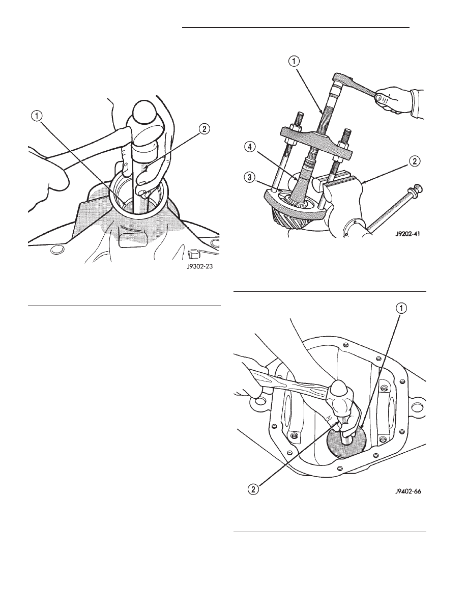
(8) Remove the rear pinion bearing cup and oil

slinger from the axle housing (Fig. 41). Use Remover
D-149 and Handle C–4171. Record the thickness of
the oil slinger for future reference.

(9) Remove the rear pinion bearing from the pin-

ion

with

Puller/Press

C–293-PA

and

Adapters

C-293-39 (Fig. 42).

Place 4 adapter blocks so they do not damage

the bearing cage.

(10) Remove the pinion depth shim/oil baffle from

the pinion shaft. Record the thickness of the depth
shim/oil baffle.

INSTALLATION

NOTE: A pinion depth shim/oil baffle is placed
between the rear pinion bearing cone and pinion
gear. If the factory installed ring and pinion gears
are reused, the pinion depth shim/oil baffle should
not require replacement. Refer to Pinion Gear Depth
to select the proper thickness shim before installing
pinion gear.

(1) Install a new oil slinger of the same thickness

as the original into the rear pinion bearing bore of
the axle housing.

(2) Apply Mopar

t Door Ease, or equivalent, stick

lubricant to outside surface of rear pinion bearing
cup. Install the bearing cup with Installer D-146 and
Handle C–4171 (Fig. 43). Verify cup is correctly
seated.

Fig. 41 Rear Bearing Cup Removal

1 – DRIVER
2 – HANDLE

Fig. 42 Rear Bearing Removal

1 – SPECIAL TOOL C-293–PA
2 – VISE
3 – ADAPTERS
4 – DRIVE PINION GEAR SHAFT

Fig. 43 Rear Pinion Bearing Cup Installation

1 – INSTALLER
2 – HANDLE

3 - 38

TUBE, 181, AND 186 FBI AXLE

XJ

REMOVAL AND INSTALLATION (Continued)

(3) Apply Mopar

t Door Ease, or equivalent, stick

lubricant to outside surface of front pinion bearing
cup. Install the bearing cup with Installer D-144 and
Handle C–4171 (Fig. 44).

(4) Install front pinion bearing, and oil slinger, if

equipped.

(5) Apply a light coating of gear lubricant on the

lip of pinion seal. Install seal with Installer C-3972-A
and Handle C–4171 (Fig. 45).

(6) Install the rear pinion bearing and pinion

depth shim/oil baffle onto the pinion gear with
Installer W-262 and a shop press (Fig. 46).

(7) Install pinion bearing preload shims onto the

pinion gear (Fig. 47).

(8) Install pinion gear in housing.
(9) Install yoke with Installer W-162-B, Cup 8109,

and Holder 6958 (Fig. 48).

Fig. 44 Pinion Outer Bearing Cup Installation

1 – INSTALLER
2 – HANDLE

Fig. 45 Pinion Seal Installation

1 – SPECIAL TOOL C-4171
2 – SPECIAL TOOL C-3972–A

Fig. 46 Rear Pinion Bearing Installation

1 – PRESS
2 – INSTALLATION TOOL
3 – PINION DEPTH SHIM/OIL BAFFLE
4 – DRIVE PINION
5 – DRIVE PINION SHAFT REAR BEARING

XJ

TUBE, 181, AND 186 FBI AXLE

3 - 39

REMOVAL AND INSTALLATION (Continued)

(10) Install the pinion washer and a new nut on

the pinion gear. Tighten the nut to 217 N·m (160 ft.
lbs.).

CAUTION: Never

loosen

pinion

gear

nut

to

decrease pinion gear bearing rotating torque and
never exceed specified preload rotating torque.

(11) Check bearing preload torque with an inch

pound torque wrench (Fig. 49). The torque necessary
to rotate the pinion gear should be:

• Original Bearings—1 to 2 N·m (10 to 20 in. lbs.).

• New Bearings—1.5 to 4 N·m (15 to 35 in. lbs.).
(12) If

rotating

torque

is

above

the

desired

amount, remove the pinion yoke and increase the
preload shim pack thickness. Increasing the shim
pack thickness 0.025 mm (0.001 in.) will decrease the
rotating torque approximately 0.9 N·m (8 in. lbs.).

(13) Tighten pinion shaft nut in 6.8 N·m (5 ft. lbs.)

increments until the maximum tightening or desired
rotating torque is reached. Maximum tightening
torque is 271 N·m (200 ft.lbs.).

Fig. 47 Pinion Preload Shims–Typical

1 – PINION PRELOAD SHIMS
2 – FRONT BEARING CUP
3 – SLINGER
4 – PINION YOKE

5 – WASHER
6 – PINION NUT
7 – PINION OIL SEAL
8 – FRONT BEARING CONE

Fig. 48 Pinion Yoke Installation

1 – PINION YOKE
2 – AXLE HOUSING

3 - 40

TUBE, 181, AND 186 FBI AXLE

XJ

REMOVAL AND INSTALLATION (Continued)

(14) If the maximum tightening torque is reached

prior to achieving the desired rotating torque, remove
the pinion yoke and decrease the thickness of the
preload shim pack. Decreasing the shim pack thick-
ness 0.025 mm (0.001 in.) will increase the rotating
torque approximately 0.9 N·m (8 in. lbs.).

(15) Install differential assembly.

186 FBI PINION

The ring gear and pinion are serviced as a matched

set. Do not replace the pinion without replacing the
ring gear.

REMOVAL

(1) Remove differential assembly from axle hous-

ing.

(2) Mark pinion yoke and propeller shaft for

installation alignment.

(3) Disconnect propeller shaft from pinion yoke.

Using suitable wire, tie propeller shaft to underbody.

(4) Using Holder 6958 to the hold yoke, remove

the pinion nut and washer (Fig. 50).

(5) Using Remover C–452 and Holder C-3281,

remove the pinion yoke from pinion shaft (Fig. 51).

Fig. 49 Check Pinion Gear Rotating Torque

1 – in. lbs. TORQUE WRENCH
2 – PINION YOKE

Fig. 50 Pinion Yoke Holder—Typical

1 – 1 in. PIPE
2 – PINION YOKE
3 – SPECIAL TOOL

6958

4 – LOWER CONTROL ARM

Fig. 51 Pinion Yoke Removal

1 – SPECIAL TOOL C-3281
2 – YOKE
3 – SPECIAL TOOL C-452

XJ

TUBE, 181, AND 186 FBI AXLE

3 - 41

REMOVAL AND INSTALLATION (Continued)


Content   ..  20  21  22  23   ..