Jeep XJ. Manual - part 20


  Index      Jeep     Jeep XJ - service repair manual 2001 year


Search            


Content   ..  18  19  20  21   ..


Jeep XJ. Manual - part 20


(14) Add gear lubricant, if necessary. Refer to

Lubricant Specifications of this section for lubricant
requirements.

(15) Install wheel and tire assemblies.
(16) Lower vehicle.

HUB BEARING AND AXLE SHAFT

If the axle shaft and hub bearing are being

removed in order to service another component, the
axle shaft and hub bearing can be removed as an
assembly.

REMOVAL

(1) Raise and support the vehicle.
(2) Remove the wheel and tire assembly.
(3) Remove the brake caliper and rotor. Refer to

Group 5, Brakes, for proper procedures.

(4) Remove ABS wheel speed sensor, if necessary.

Refer to Group 5, Brakes, for proper procedures.

(5) Remove the cotter pin, nut retainer, and axle

hub nut (Fig. 22), if necessary.

(6) Remove the hub to knuckle bolts (Fig. 23).
(7) Remove the hub from the steering knuckle and

axle shaft, if necessary.

(8) Remove hub bearing and axle shaft assembly

(Fig. 24), or axle shaft from axle. Avoid damaging
the axle shaft oil seals in the axle housing.

(9) Remove the brake rotor shield from the hub

bearing or knuckle (Fig. 22).

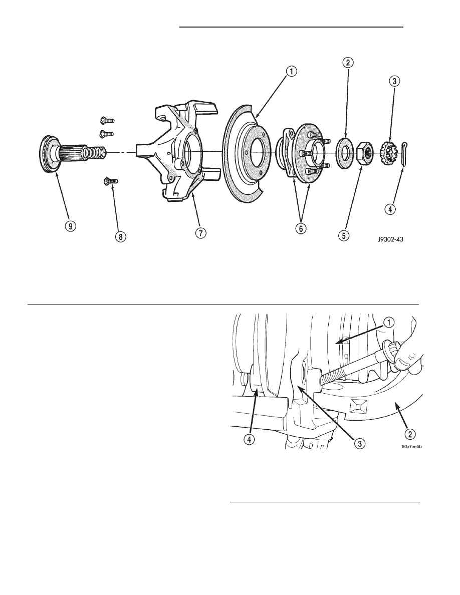
Fig. 22 Hub, Knuckle and Axle Shaft

1 – BRAKE SHIELD
2 – WASHER
3 – RETAINER
4 – COTTER PIN
5 – NUT

6 – HUB AND BEARING ASSEMBLY
7 – STEERING KNUCKLE
8 – BOLT
9 – TONE WHEEL (ABS)

Fig. 23 Hub Bearing Bolts

1 – AXLE SHAFT
2 – AXLE
3 – KNUCKLE
4 – HUB BEARING

3 - 30

TUBE, 181, AND 186 FBI AXLE

XJ

REMOVAL AND INSTALLATION (Continued)

INSTALLATION

(1) Thoroughly clean the axle shaft (Fig. 22) and

apply a thin film of Mopar

t Wheel Bearing Grease,

or equivalent, to the shaft splines, seal contact sur-
face, and hub bore.

(2) Install the brake rotor shield to the knuckle.
(3) Install the hub bearing and axle shaft assem-

bly, or axle shaft, into the housing and differential
side gears. Avoid damaging the axle shaft oil seals in
the axle housing.

(4) Install the hub bearing, if necessary.
(5) Install the hub to knuckle bolts and tighten to

102 N·m (75 ft. lbs.) torque.

(6) Install the hub washer and nut, if necessary.

Tighten the hub nut to 237 N·m (175 ft. lbs.) torque.
Install the nut retainer and a new cotter pin (Fig.
22).

(7) Install ABS wheel speed sensor, if necessary.

Refer to Group 5, Brakes, for proper procedures.

(8) Install the brake rotor and caliper. Refer to

Group 5, Brakes, for proper procedures.

(9) Install the wheel and tire assembly.
(10) Remove support and lower the vehicle.

STEERING KNUCKLE AND BALL STUDS

Ball stud service procedures below require removal

of the hub bearing and axle shaft. Removal and
installation of upper and lower ball studs require the
use of Tool Kit 6289.

KNUCKLE REMOVAL

(1) Remove hub bearing and axle shaft.
(2) Disconnect the tie-rod or drag link from the

steering knuckle arm. Refer to Group 2, Suspension,
for proper procedures.

(3) Remove the cotter pins from the upper and

lower ball studs.

(4) Remove the upper and lower ball stud nuts.
(5) Strike the steering knuckle with a brass ham-

mer to loosen knuckle from the ball studs. Remove
knuckle from ball studs (Fig. 25).

Fig. 24 Hub Bearing and Axle Assembly

1 – AXLE
2 – KNUCKLE
3 – HUB BEARING
4 – AXLE SHAFT

Fig. 25 Steering Knuckle Removal/Installation

1 – AXLE YOKE
2 – UPPER BALL STUD
3 – LOWER BALL STUD
4 – STEERING KNUCKLE

XJ

TUBE, 181, AND 186 FBI AXLE

3 - 31

REMOVAL AND INSTALLATION (Continued)

UPPER BALL STUD REPLACEMENT

(1) Position tools as shown to remove and install

ball stud (Fig. 26).

LOWER BALL STUD REPLACEMENT

(1) Position tools as shown to remove and install

ball stud (Fig. 27).

KNUCKLE INSTALLATION

(1) Position the steering knuckle on the ball studs.

(2) Install and tighten the bottom retaining nut to

109 N·m (80 ft. lbs.) torque. Install new cotter pin.

(3) Install and tighten the top retaining nut to 101

N·m (75 ft. lbs.) torque. Install new cotter pin.

(4) Install the hub bearing and axle shaft.
(5) Connect the tie-rod or drag link end to the

steering knuckle arm. Refer to Group 2, Suspension,
for proper procedures.

Fig. 26 Upper Ball Stud Remove/Install

3 - 32

TUBE, 181, AND 186 FBI AXLE

XJ

REMOVAL AND INSTALLATION (Continued)

AXLE BUSHING REPLACEMENT

Refer to Group 2, Suspension, for the proper axle

bushing procedures.

DIFFERENTIAL

REMOVAL

(1) Raise and support vehicle.
(2) Remove the lubricant fill hole plug from the

differential housing cover.

(3) Remove the differential housing cover and

allow fluid to drain.

(4) Remove hub bearings and axle shafts.
(5) Note the installation reference letters stamped

on the bearing caps and housing machined sealing
surface (Fig. 28).

(6) Loosen the differential bearing cap bolts.
(7) Position Spreader W–129–B, utilizing some

items from Adapter Kit 6987, with the tool dowel
pins seated in the locating holes (Fig. 29). Install the
holddown clamps and tighten the tool turnbuckle fin-
ger–tight.

Fig. 27 Lower Ball Stud Remove/Install

1 – SPECIAL TOOL 6289–12
2 – SPECIAL TOOL 6289–4
3 – SPECIAL TOOL 4212F

4 – SPECIAL TOOL 4212F
5 – SPECIAL TOOL 6289–1
6 – SPECIAL TOOL 6289–3

Fig. 28 Bearing Cap Identification

1 – INSTALLATION REFERENCE LETTERS
2 – INSTALLATION REFERENCE LETTERS

XJ

TUBE, 181, AND 186 FBI AXLE

3 - 33

REMOVAL AND INSTALLATION (Continued)


Content   ..  18  19  20  21   ..