Jeep XJ. Manual - part 14


  Index      Jeep     Jeep XJ - service repair manual 2001 year


Search            


Content   ..  12  13  14  15   ..


Jeep XJ. Manual - part 14


(4) Refer to Runout Specifications chart.
(5) If the propeller shaft runout is out of specifica-

tion, remove the propeller shaft, index the shaft 180°,
and re-install the propeller shaft. Measure shaft
runout again.

(6) If the propeller shaft runout is now within

specifications, mark the shaft and yokes for proper
orientation.

(7) If the propeller shaft runout is not within spec-

ifications, verify that the runout of the transmission/
transfer case and axle are within specifications.
Correct as necessary and re-measure propeller shaft
runout.

(8) Replace the propeller shaft if the runout still

exceeds the limits.

SERVICE PROCEDURES

DRIVELINE ANGLE MEASUREMENT
PREPARATION

Before measuring universal joint angles, the fol-

lowing must be done;

• Inflate all tires to correct pressure.

• Check the angles in the same loaded or

unloaded condition as when the vibration occurred.
Propeller shaft angles change according to the
amount of load in the vehicle.

• Check the condition of all suspension compo-

nents and verify all fasteners are torqued to specifi-
cations.

• Check the condition of the engine and transmis-

sion mounts and verify all fasteners are torqued to
specifications.

PROPELLER SHAFT ANGLE MEASUREMENT

To accurately check driveline alignment, raise and

support the vehicle at the axles as level as possible.
Allow the wheels and propeller shaft to turn.

(1) Remove any external bearing snap rings, if

equipped, from universal joint so protractor base sits
flat.

(2) Rotate the shaft until transmission/transfer

case output yoke bearing is facing downward.

Always make measurements from front to

rear. Also, be sure to take all measurements
while working from the same side of the vehi-
cle.

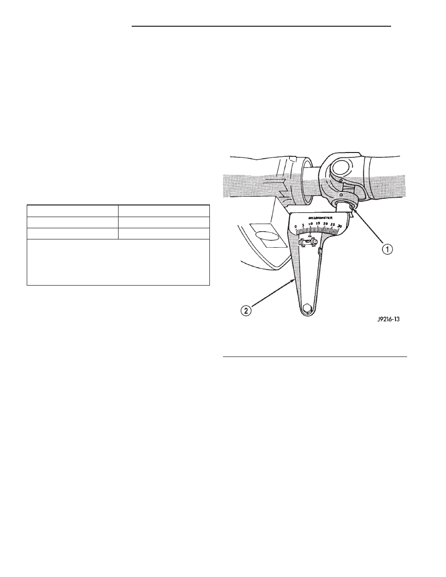
(3) Place Inclinometer on yoke bearing (A) parallel

to the shaft (Fig. 9). Center bubble in sight glass and
record measurement.

This measurement will give you the transmis-

sion or Output Yoke Angle (A).

(4) Rotate propeller shaft 90 degrees and place

Inclinometer on yoke bearing parallel to the shaft
(Fig. 10). Center bubble in sight glass and record
measurement. This measurement can also be taken
at the rear end of the shaft.

This measurement will give you the Propeller

Shaft Angle (C).

(5) Subtract smaller figure from larger (C minus

A) to obtain Transmission Output Operating Angle.

(6) Rotate propeller shaft 90 degrees and place

Inclinometer on pinion yoke bearing parallel to the
shaft (Fig. 11). Center bubble in sight glass and
record measurement.

RUNOUT SPECIFICATIONS

Front of Shaft

0.020 in. (0.50 mm)

Center of Shaft

0.025 in. (0.63 mm)

Rear of Shaft

0.020 in. (0.50 mm)

Measure front/rear runout approximately 3 inches
(76 mm) from the weld seam at each end of the shaft
tube for tube lengths over 30 inches. For tube lengths
under 30 inches, the maximum allowed runout is
0.020 in. (0.50 mm) for the full length of the tube.

Fig. 9 Front (Output) Angle Measurement (A)

1 – SLIP YOKE BEARING CAP
2 – SPECIAL TOOL 7663 (J-23498A)

3 - 6

PROPELLER SHAFTS

XJ

DIAGNOSIS AND TESTING (Continued)

This measurement will give you the pinion

shaft or Input Yoke Angle (B).

(7) Subtract smaller figure from larger (C minus

B) to obtain axle Input Operating Angle.

Refer to rules given below and the example in

(Fig. 12) for additional information.

Fig. 11 Rear (Input) Angle Measurement (B)

1 – PINION YOKE BEARING CAP
2 – SPECIAL TOOL 7663 (J-23498A)

Fig. 12 Universal Joint Angle Example

1 – 4.9° Angle (C)
2 – 3.2° Angle (B)
3 – Input Yoke

4 – 3.0° Angle (A)
5 – Output Yoke

Fig. 10 Propeller Shaft Angle Measurement (C)

1 – SHAFT YOKE BEARING CAP
2 – SPECIAL TOOL 7663 (J23498–A)

XJ

PROPELLER SHAFTS

3 - 7

SERVICE PROCEDURES (Continued)

• Good cancellation of U–joint operating angles

(within 1°).

• Operating angles less than 3°.

• At least 1/2 of one degree continuous operating

(propeller shaft) angle.

REMOVAL AND INSTALLATION

FRONT PROPELLER SHAFT

REMOVAL

(1) Hoist and support vehicle on safety stands.
(2) Remove the crossmember/skid plate as neces-

sary to gain access to the propeller shaft.

(3) Shift the transmission and transfer case, if nec-

essary, into the Neutral position.

(4) Using a suitable marker, mark a line across

the yoke at the transfer case, the link yoke, and pro-
peller shaft yoke at the rear of the front propeller
shaft for installation reference (Fig. 13).

(5) Mark a line across the propeller shaft yoke and

the pinion shaft yoke for installation reference.

(6) Remove the U-joint strap bolts at the pinion

shaft yoke (Fig. 14).

(7) Remove bolts holding rear universal joint to

the transfer case yoke.

(8) Separate the rear universal joint from the

transfer case yoke.

(9) Push rear of propeller shaft upward to clear

transfer case yoke.

(10) Separate front universal joint from front axle.
(11) Separate propeller shaft from vehicle.

INSTALLATION

(1) Position front propeller shaft under vehicle

with rear universal joint over the transfer case yoke.

(2) Place front universal joint into the axle pinion

yoke.

(3) Align mark on the rear link yoke and universal

joint to the mark on the transfer case yoke (Fig. 13).

(4) Loosely install bolts to hold universal joint to

transfer case yoke.

(5) Align mark on front universal joint to the mark

on the axle pinion yoke.

(6) Tighten the U-joint strap/clamp bolts at the

axle yoke to 19 N·m (14 ft. lbs.) torque.

(7) Tighten the universal joint to transfer case

bolts to 27 N·m (20 ft. lbs.) torque.

(8) Lower the vehicle.

REAR PROPELLER SHAFT

REMOVAL

(1) Shift the transmission and transfer case into

Neutral.

(2) Hoist and support vehicle on safety stands.
(3) Scribe alignment marks at the pinion shaft and

at each end of the propeller shaft. These marks will
be used for installation reference.

(4) Remove the U-joint strap bolts at the pinion

shaft yoke.

(5) Pry open clamp holding the dust boot to propel-

ler shaft yoke (Fig. 15).

(6) Slide the slip yoke off of the transmission/

transfer case output shaft and remove the propeller
shaft (Fig. 16).

Fig. 13 Reference Marks on Yokes

1 – REFERENCE MARKS

Fig. 14 Front Propeller Shaft

1 – FRONT AXLE
2 – BOOT
3 – PROPELLER SHAFT
4 – CV-JOINT
5 – TRANSFER CASE
6 – BOOT
7 – SLINGER
8 – CLAMP
9 – YOKE

3 - 8

PROPELLER SHAFTS

XJ

SERVICE PROCEDURES (Continued)

INSTALLATION

(1) Slide the slip yoke on the transmission/transfer

case output shaft. Align the installation reference
marks at the axle yoke and install the propeller shaft
(Fig. 16).

(2) Tighten the U-joint strap/clamp bolts at the

axle yoke to 19 N·m (14 ft. lbs.) torque.

(3) Crimp clamp to hold dust boot to propeller

shaft yoke (Fig. 17).

(4) Lower the vehicle.

DISASSEMBLY AND ASSEMBLY

SINGLE CARDAN UNIVERSAL JOINT

DISASSEMBLY

Individual components of cardan universal joints

are not serviceable. If worn or leaking, they must be
replaced as an assembly.

(1) Remove the propeller shaft.
(2) Using a soft drift, tap the outside of the bear-

ing cap assembly to loosen snap ring.

(3) Remove snap rings from both sides of yoke

(Fig. 18).

Fig. 15 Dust Boot Clamp

1 – SLINGER
2 – BOOT
3 – AWL
4 – TRANSFER CASE

Fig. 16 Rear Propeller Shaft

1 – CLAMP
2 – YOKE
3 – PROPELLER SHAFT
4 – AXLE YOKE
5 – CLAMP
6 – OUTPUT SHAFT
7 – BOOT

Fig. 17 Crimping Dust Boot Clamp

1 – SPECIAL TOOL C-4975–A
2 – SLINGER
3 – BOOT
4 – CLAMP

Fig. 18 Remove Snap Ring

1 – SNAP RING

XJ

PROPELLER SHAFTS

3 - 9

REMOVAL AND INSTALLATION (Continued)


Content   ..  12  13  14  15   ..