Jeep Wrangler TJ. Manual - part 593
INSTALLATION
CAUTION: The instrument panel air outlets can only
be installed in one direction. If an air outlet is not
properly oriented prior to installation, damage to
the outlet will occur.
NOTE: Each air outlet is retained into the outlet
opening by two pivot shafts. One pivot shaft is
larger than the other. The air outlet must be first
installed onto the larger pivot shaft, then snapped
into place over the smaller pivot shaft.
(1) Install the air outlet onto the larger pivot shaft
located in the instrument panel outlet opening.
(2) Gently push the air outlet onto the smaller
pivot shaft until it snaps into position.
BLOWER MOTOR
DESCRIPTION
The blower motor (Fig. 3)is a 12-volt, direct current
(DC) motor mounted within a plastic housing with an
integral wire connector and squirrel cage-type blower
wheel that is secured to the blower motor shaft. The
blower motor wheel is located in the HVAC air inlet
housing which is mounted to the passenger side end
of the HVAC housing.
The blower motor can be accessed for service from
underneath the instrument panel.
OPERATION
The blower motor is used to control the velocity of
air moving through the HVAC housing by spinning
the blower wheel within the HVAC air inlet housing
at the selected speed.
The blower motor will operate whenever the igni-
tion switch is in the On position and the blower
motor control in any position except Off. Blower
motor speed is controlled by regulating the path to
ground through the blower motor resistor and
through the blower motor control located within the
A/C-heater control.
The blower motor and blower motor wheel are fac-
tory balanced and cannot be adjusted or repaired. If
faulty or damaged, the blower motor and blower
wheel must be replaced as an assembly.
DIAGNOSIS AND TESTING
BLOWER MOTOR
WARNING: On vehicles equipped with airbags, dis-
able the airbag system before attempting any steer-
ing wheel, steering column, or instrument panel
component diagnosis or service. Disconnect and
isolate the negative battery (ground) cable, then
wait two minutes for the airbag system capacitor to
discharge before performing further diagnosis or
service. Failure to take the proper precautions
could result in accidental airbag deployment and
possible personal injury or death.
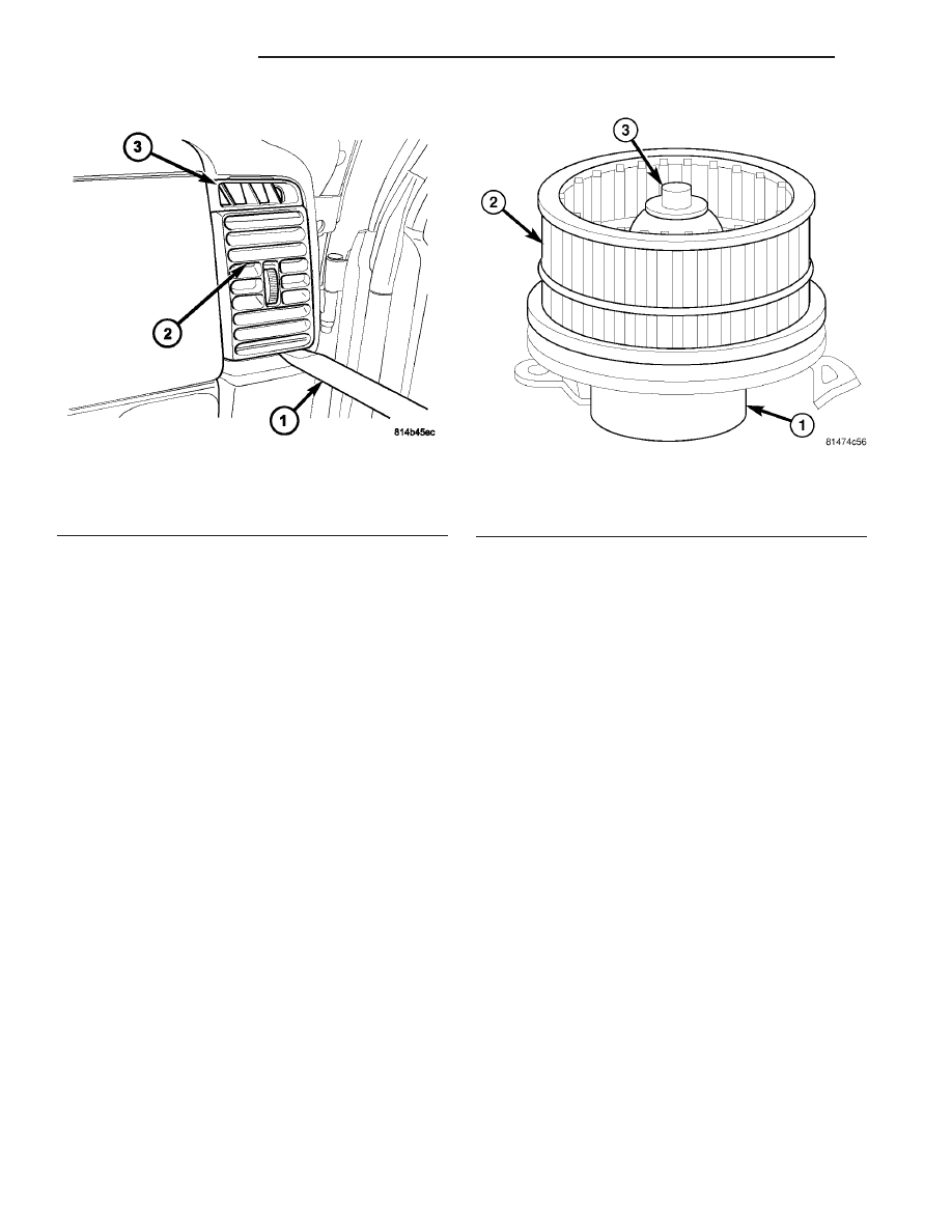
Fig. 2 Instrument Panel Air Outlets
1 - TRIM STICK
2 - PANEL AIR OUTLETS (4)
3 - PANEL OUTLET HOUSING
Fig. 3 Blower Motor - Typical
1 - BLOWER MOTOR
2 - BLOWER WHEEL
3 - MOTOR SHAFT
24 - 38
DISTRIBUTION
TJ
AIR OUTLETS (Continued)