Jeep Wrangler TJ. Manual - part 585
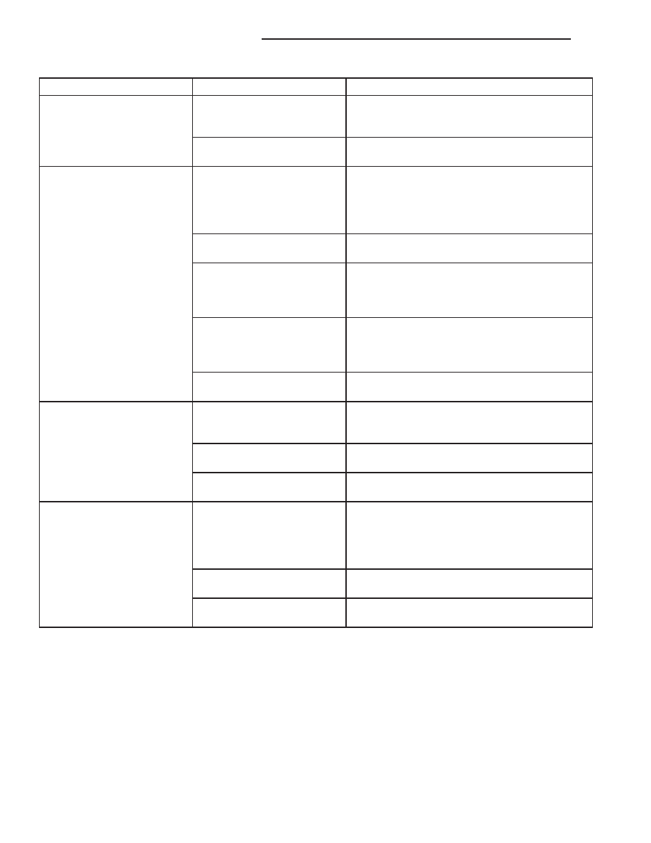
Condition
Possible Causes
Correction
3. Refrigerant flow through
the A/C evaporator is
restricted.
3. See A/C Evaporator in this group. Replace the
restricted A/C evaporator, if required.
4. Faulty A/C compressor.
4. See A/C Compressor in this group. Replace
the A/C compressor, if required.
The low side pressure is
normal or slightly high, and
the high side pressure is too
high.
1. A/C condenser air flow
restricted.
1. Check the A/C condenser for damaged fins,
foreign objects obstructing air flow through the
condenser fins, and missing or improperly
installed air seals. Clean, repair, or replace
components as required.
2. Inoperative radiator
cooling fan.
2. Test the radiator cooling fan and replace, if
required. Refer to Group 7.
3. Refrigerant system
overcharged.
3. See Refrigerant System Charge in this group.
Recover the refrigerant from the refrigerant
system. Charge the refrigerant system to the
proper level, if required.
4. Air in the refrigerant
system.
4. See Refrigerant System Leaks in this group.
Test the refrigerant system for leaks. Repair,
evacuate and charge the refrigerant system, if
required.
5. Engine overheating.
5. Test the engine cooling system and repair, if
required. Refer to Group 7.
The low side pressure is too
high, and the high side
pressure is too low.
1. Accessory drive belt
slipping.
1. Inspect the accessory drive belt condition and
tension. Tighten or replace the accessory drive
belt, if required. Refer to Group 7.
2. Faulty A/C orifice tube.
2. See A/C Orifice Tube in this group. Replace
the liquid line, if required.
3. Faulty A/C compressor.
3. See A/C Compressor in this group. Replace
the A/C compressor, if required.
The low side pressure is too
low, and the high side
pressure is too high.
1. Restricted refrigerant flow
through the refrigerant lines.
1. See Liquid Line and Suction and Discharge
Line in this group. Inspect the refrigerant lines for
kinks, tight bends or improper routing. Correct
the routing or replace the refrigerant line, if
required.
2. Restricted refrigerant flow
through the A/C orifice tube.
2. See A/C Orifice Tube in this group. Replace
the liquid line, if required.
3. Restricted refrigerant flow
through the A/C condenser.
3. See A/C Condenser in this group. Replace the
restricted condenser, if required.
24 - 6
HEATING & AIR CONDITIONING
TJ
HEATING & AIR CONDITIONING (Continued)