Jeep Wrangler TJ. Manual - part 584


  Index      Jeep     Jeep Wrangler TJ - service repair manual 2005 year


Search            


Content   ..  582  583  584  585   ..


Jeep Wrangler TJ. Manual - part 584


each outboard end of the instrument panel, above the
panel outlets.

• Panel Outlets - There are four panel outlets in

the instrument panel, one located near each outboard
end of the instrument panel facing the rear of the
vehicle and two located near the top of the instru-
ment panel center bezel.

• Front Floor Outlets - There are two front floor

outlets, one located above each side of the floor panel
center tunnel near the dash panel.

OPERATION

Both the single zone manual temperature control

(MTC) heating-A/C system and the heater-only sys-
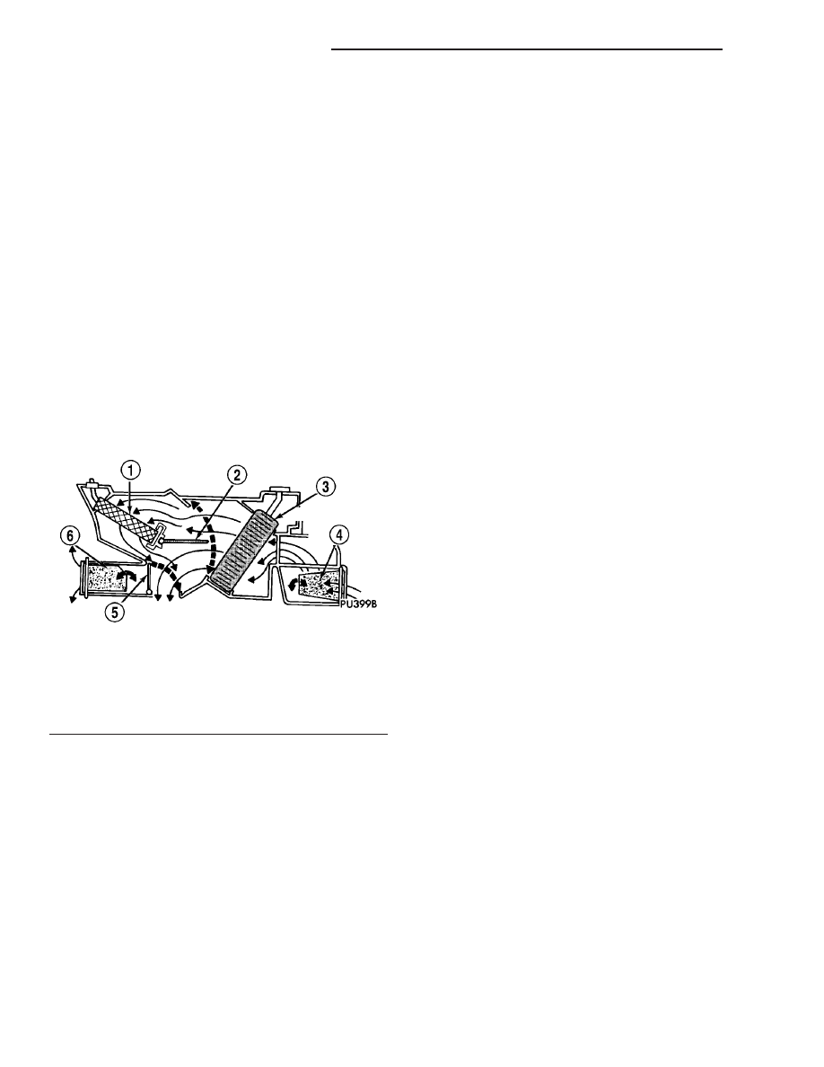
tem are blend-air type systems. In a blend-air heat-
ing-A/C system (Fig. 2), a blend-air door controls the
amount of conditioned air that is allowed to flow
through, or around, the heater core. The temperature
control determines the discharge air temperature by
operating the blend door actuator, which move the
blend-air door. This design allows almost immediate
control of output air temperatures.

The heating and A/C systems pulls outside (ambi-

ent) air through the cowl opening at the base of the
windshield, then into the air inlet housing above the
heating, ventilation and air conditioning (HVAC)
housing. On models equipped with A/C, the air
passes through the A/C evaporator. Air flow can be
directed either through or around the heater core.
This is done by adjusting the blend door with the
temperature control knob on the A/C-heater control
in the instrument panel. The air flow can then be
directed from the panel, floor and defrost outlets in
various combinations using the mode control located
on the A/C-heater control. Air flow velocity can be
adjusted with the blower fan speed control located on
the A/C-heater control.

On models equipped with A/C, the outside air

intake can be shut off by selecting the Recirculation
Mode. This will operate a vacuum actuated recircu-
lating-air door that closes off the fresh air intake and
recirculates the air that is already inside the vehicle.

The A/C compressor can be engaged by turning the

mode control clockwise from the Off position. It can
also be engaged by placing the mode control in the
mix to defrost positions. This will remove heat and
humidity from the air before it is directed through or
around the heater core. The mode control on the A/C-
heater control is used to also direct the conditioned
air to the selected system outlets. The mode control
uses engine vacuum to control the mode-air doors.

The defroster outlet receives airflow from the

HVAC housing through the molded plastic defroster
duct, which is connected to the HVAC housing
defroster outlet. The airflow from the defroster outlet
is directed by fixed vanes in the defroster grille and
cannot be adjusted.

The side window demisters receive airflow from the

HVAC housing through the molded plastic defroster
duct, two molded plastic demister ducts and two
molded plastic demister outlets. The airflow from the
side window demister outlets is directed by fixed
vanes in the demister grilles and cannot be adjusted.
The demisters direct air from the HVAC housing
through the outlets located on the top corners of the
instrument panel. The demisters operate when the
mode control is positioned in the floor-defrost and
defrost-only settings. Some air may be noticeable
from the demister outlets when the mode control is
in the bi-level to floor positions.

The four instrument panel outlets receive airflow

from the HVAC housing through a single molded
plastic instrument panel duct. The single instrument
panel duct directs airflow to all of the instrument
panel outlets. Each of these outlets can be individu-
ally adjusted to direct the flow of air.

The floor outlets receive airflow from the HVAC

housing through the floor distribution duct. The front
floor outlets are integral to the molded plastic floor
distribution duct, which is secured to the bottom of
the HVAC housing. The floor outlets cannot be
adjusted.

Fig. 2 Typical Blend-Air HVAC System

1 - HEATER CORE
2 - BLEND-AIR DOOR
3 - A/C EVAPORATOR
4 - RECIRCULATION-AIR DOOR
5 - FLOOR MODE-AIR DOOR
6 - PANEL/DEFROST MODE-AIR DOOR

24 - 2

HEATING & AIR CONDITIONING

TJ

HEATING & AIR CONDITIONING (Continued)

NOTE: It is important to keep the air intake opening
clear of debris. Leaf particles and other debris that
is small enough to pass through the cowl opening
screen can accumulate within the HVAC housing.
The closed, warm, damp and dark environment cre-
ated within the housing is ideal for the growth of
certain molds, mildews and other fungi. Any accu-
mulation of decaying plant matter provides an addi-
tional food source for fungal spores, which enter
the housing with the fresh intake-air. Excess debris,
as well as objectionable odors created by decaying
plant matter and growing fungi can be discharged
into the passenger compartment during heater-A/C
operation if the air intake opening is not kept clear
of debris.

The A/C system on models so equipped is designed

for the use of non-CFC, R-134a refrigerant and uses
an A/C fixed orifice tube located in the liquid line to
meter the flow of refrigerant to the A/C evaporator.
The A/C evaporator cools and dehumidifies the
incoming air prior to blending it with the heated air.
To maintain minimum evaporator temperature and
prevent evaporator freezing, the A/C clutch is cycled
on and off by the A/C low pressure switch mounted
on the accumulator.

DIAGNOSIS AND TESTING

A/C PERFORMANCE

The A/C system is designed to provide the passen-

ger compartment with low temperature and low
humidity air. The A/C evaporator, located in the
HVAC housing is cooled to temperatures near the
freezing point. As warm damp air passes over the
fins of the A/C evaporator, the air transfers its heat
to the refrigerant in the evaporator coils and the
moisture in the air condenses on the evaporator fins.
During periods of high heat and humidity, an A/C
system will be more effective in the Recirculation
mode (max-A/C). With the system in the Recircula-
tion mode, only air from the passenger compartment
passes through the A/C evaporator. As the passenger
compartment air dehumidifies, the A/C system per-
formance levels rise.

Humidity has an important bearing on the temper-

ature of the air delivered to the interior of the vehi-
cle. It is important to understand the effect that
humidity has on the performance of the A/C system.
When humidity is high, the A/C evaporator has to
perform a double duty. It must lower the air temper-
ature, and it must lower the temperature of the
moisture in the air that condenses on the evaporator
fins. Condensing the moisture in the air transfers
heat energy into the evaporator fins and coils. This
reduces the amount of heat the A/C evaporator can
absorb from the air. High humidity greatly reduces
the ability of the A/C evaporator to lower the temper-
ature of the air.

However, evaporator capacity used to reduce the

amount of moisture in the air is not wasted. Wring-
ing some of the moisture out of the air entering the
vehicle adds to the comfort of the passengers.
Although, an owner may expect too much from their
A/C system on humid days. A performance test is the
best way to determine whether the system is per-
forming up to design standards. This test also pro-
vides valuable clues as to the possible cause of
trouble with the A/C system. The ambient air tem-
perature in the location where the vehicle will be
tested must be a minimum of 21° C (70° F) for this
test.

A/C PERFORMANCE TEST

WARNING: Refer to the applicable warnings and
cautions for this system before performing the fol-
lowing operation (Refer to 24 - HEATING & AIR
CONDITIONING/PLUMBING - WARNINGS) and (Refer
to 24 - HEATING & AIR CONDITIONING/PLUMBING -
CAUTIONS). Failure to follow the warnings and cau-
tions could result in possible personal injury or
death.

NOTE: When connecting the service equipment
coupling to the line fitting, verify that the valve of
the coupling is fully closed. This will reduce the
amount of effort required to make the connection.

TJ

HEATING & AIR CONDITIONING

24 - 3

HEATING & AIR CONDITIONING (Continued)

(1) Connect a tachometer and a manifold gauge set

or an A/C recycling/charging station.

(2) Set the mode control to the Recirculation mode,

the temperature control to the full cool position, and
the blower fan to the highest speed position.

(3) Start the engine and hold at 1,000 rpm with

the A/C clutch engaged.

(4) The engine should be warmed up to operating

temperature with the doors closed and windows
open.

(5) Insert a thermometer in the driver side center

panel air outlet and operate the engine for five min-
utes.

(6) The A/C clutch may cycle, depending upon the

ambient temperature and humidity. If the A/C clutch
cycles, unplug the wire harness connector from the
A/C low pressure switch located on the accumulator
(Fig. 3), then place a jumper wire across the termi-
nals of the wire harness connector for the switch.

(7) With the A/C clutch engaged, record the air

outlet discharge temperature, the discharge pressure
(high side service port) and the suction pressure (low
side service port). Compare the air temperature at

the center panel outlet and the A/C compressor dis-
charge pressure (high side) to the A/C Performance
Temperature and Pressure chart.

A/C PERFORMANCE TEMPERATURE AND PRESSURE

Ambient Air
Temperature

21° C

(70° F)

27° C

(80° F)

32° C

(90° F)

38° C

(100° F)

43° C

(110° F)

Air Temperature at
Center Panel Outlet

-3 to 3° C

(27 to 38° F)

1 to 7° C

(33 to 44° F)

3 to 9° C

(37 to 48° F)

6 to 13° C

(43 to 55° F)

10 to 18° C

(50 to 64° F)

Evaporator Inlet
Pressure at Charge
Port

179 to 241 kPa

(26 to 35 psi)

221 to 283 kPa

(32 to 41 psi)

262 to 324

kPa

(38 to 47 psi)

303 to 365

kPa

(44 to 53 psi)

345 to 414 kPa

(50 to 60 psi)

Compressor
Discharge Pressure

1240 to 1655

kPa

(180 to 240

psi)

1380 to 1790

kPa

(200 to 260

psi)

1720 to 2070

kPa

(250 to 300

psi)

1860 to 2345

kPa

(270 to 340

psi)

2070 to 2690

kPa

(300 to 390 psi)

(8) If the air outlet temperature fails to meet the

specifications in the A/C Performance Temperature
and Pressure chart, or if the A/C compressor dis-
charge pressure is high, refer to the A/C Pressure
Diagnosis chart.

Fig. 3 A/C Low Pressure Switch - Typical

1 - A/C LOW PRESSURE SWITCH
2 - ACCUMULATOR

24 - 4

HEATING & AIR CONDITIONING

TJ

HEATING & AIR CONDITIONING (Continued)

A/C PRESSURE DIAGNOSIS

Condition

Possible Causes

Correction

Rapid A/C clutch cycling (ten
or more cycles per minute).

1. Low refrigerant system
charge.

1. See Refrigerant System Leaks in this group.
Test the refrigerant system for leaks. Repair,
evacuate and charge the refrigerant system, if
required.

Equal pressures, but the A/C
clutch does not engage.

1. No refrigerant in the
refrigerant system.

1. See Refrigerant System Leaks in this group.
Test the refrigerant system for leaks. Repair,
evacuate and charge the refrigerant system, if
required.

2. Faulty fuse.

2. Check the fuses in the fuse block and the
power distribution center (PDC). Repair the
shorted circuit or component and replace the
fuses, if required. Refer to Group 8.

3. Faulty A/C clutch field coil.

3. See A/C Compressor Clutch in this group. Test
the A/C clutch field coil and replace, if required.

4. Faulty A/C clutch relay.

4. See A/C Clutch Relay in this group. Test the
A/C clutch relay and relay circuits. Repair the
circuits or replace the relay, if required.

5. Improperly installed or
faulty A/C low pressure
switch.

5. See A/C Low Pressure Switch in this group.
Test the A/C low pressure switch and tighten or
replace, if required.

6. Faulty A/C pressure
transducer (2.4L engine).

6. See A/C Pressure Transducer in this group.
Test the A/C pressure transducer and replace, if
required.

6. Faulty A/C high pressure
switch (4.0L engine).

6. See A/C High Pressure Switch in this group.
Test the A/C high pressure switch and replace, if
required.

7. Faulty powertrain control
module (PCM).

7. Refer to the proper Diagnostic Procedures
manual for testing of the PCM. Test the PCM and
replace, if required.

Normal pressures, but A/C
Performance Test air
temperatures at center panel
outlet are too high.

1. Excessive refrigerant oil in
system.

1. See Refrigerant Oil Level in this group.
Recover the refrigerant from the refrigerant
system and inspect the refrigerant oil content.
Restore the refrigerant oil to the proper level, if
required.

2. Blend door actuator
improperly installed or faulty.

2. See Blend Door Actuator in this group. Inspect
the actuator for proper operation and replace, if
required.

3. Blend-air door inoperative
or sealing improperly.

3. See HVAC Housing in this group. Inspect the
blend-air door for proper operation and sealing
and correct, if required.

The low side pressure is
normal or slightly low, and the
high side pressure is too low.

1. Low refrigerant system
charge.

1. See Refrigerant System Leaks in this group.
Test the refrigerant system for leaks. Repair,
evacuate and charge the refrigerant system, if
required.

2. Refrigerant flow through
the accumulator is restricted.

2. See Accumulator in this group. Replace the
restricted accumulator, if required.

TJ

HEATING & AIR CONDITIONING

24 - 5

HEATING & AIR CONDITIONING (Continued)


Content   ..  582  583  584  585   ..