Jeep Wrangler TJ. Manual - part 560


  Index      Jeep     Jeep Wrangler TJ - service repair manual 2005 year


Search            


Content   ..  558  559  560  561   ..


Jeep Wrangler TJ. Manual - part 560


QUARTER GLASS

REMOVAL

(1) Cover surface areas with protective covering to

avoid paint damage and extra clean-up time.

(2) Using a razor knife, slide the blade between

the quarter glass and the inboard edge of the reveal
molding.

(3) Cut around the interior perimeter of the reveal

molding and sever the cap of the reveal molding.

(4) Using a cold knife, cut the urethane around the

perimeter of the quarter glass.

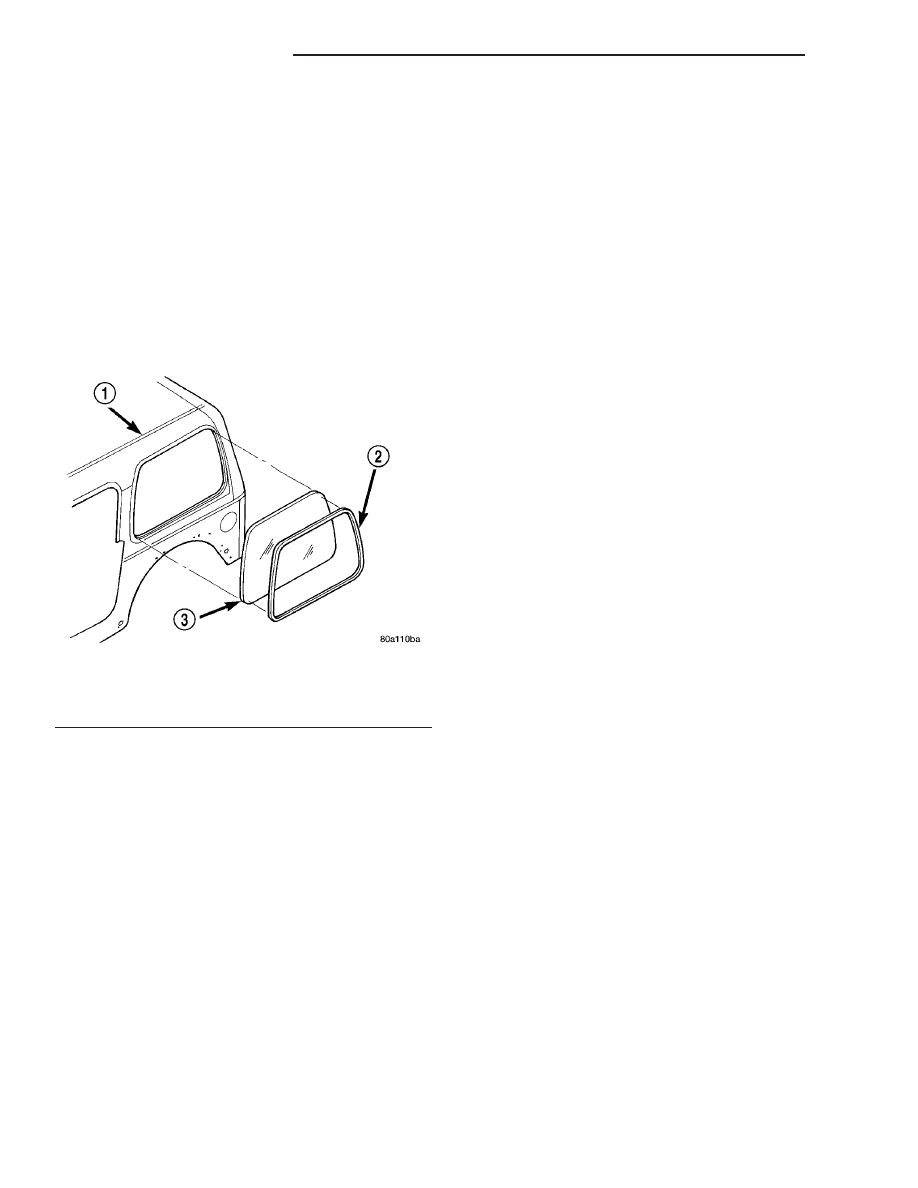
(5) Remove the quarter glass from the opening

(Fig. 1).

INSTALLATION

(1) Trim the urethane from the quarter glass open-

ing fence. Leave a 3 mm (0.1 in.) level base of ure-
thane on the quarter glass opening fence.

(2) Place replacement quarter glass into quarter

glass opening and position glass in the center of the
opening against fence.

(3) Verify the glass lays evenly against the fence at

the sides, top and bottom of the replacement quarter
glass. Next, make alignment marks on glass and top
with a grease pencil.

(4) Remove replacement quarter glass from open-

ing.

(5) Position the quarter glass inside up on a suit-

able work surface.

WARNING: DO NOT USE SOLVENT BASED GLASS
CLEANER TO CLEAN QUARTER GLASS BEFORE
APPLYING

GLASS

PREP AND

PRIMER.

POOR

ADHESION CAN RESULT.

(6) Clean inside of quarter glass with ammonia

based glass cleaner and lint-free cloth.

(7) Clean the outer edge of the window glass with

naphtha or a similar product.

(8) Apply molding to perimeter of quarter glass.

The butt weld of the molding should be centered at
the bottom edge of the quarter glass.

(9) Apply Glass Prep adhesion promoter 25 mm (1

in.) wide around perimeter of the quarter glass and
wipe with clean/dry lint-free cloth until no streaks
are visible.

(10) Apply Glass Primer 25 mm (1 in.) wide

around perimeter of quarter glass. Allow at least
three minutes drying time.

(11) Apply Pinchweld primer 15 mm (0.75 in.) wide

around the quarter glass fence. Allow at least three
minutes drying time.

(12) Apply a 10 mm (0.4 in.) diameter bead of ure-

thane to the center of the quarter glass fence surface
area.

CAUTION: Be prepared to install the quarter glass
immediately after applying the adhesive. The adhe-
sive begins to cure within 10-15 minutes.

(13) Align the quarter glass with the grease pencil

marks and position quarter glass on fence.

(14) Push the quarter glass inward until the

reveal molding is seated on the hardtop. Use care to
avoid excessive squeeze-out of adhesive.

(15) Open windows and liftgate to prevent pres-

sure build-up while the urethane is curing.

(16) Apply 150 mm (6 in.) lengths of 50 mm (2 in.)

masking tape spaced 250 mm (10 in.) apart to hold
quarter glass in place until urethane cures.

(17) After urethane has cured, remove tape strips

and water test quarter glass to verify repair.

Fig. 1 HARD TOP QUARTER GLASS

1 - HARD TOP
2 - QUARTER GLASS REVEAL MOLDING
3 - QUARTER GLASS

23 - 82

STATIONARY GLASS

TJ

WINDSHIELD

REMOVAL

The windshield is positioned in the reveal molding

and is bonded to the windshield frame with urethane
adhesive. The windshield interior trim molding is
positioned onto the inner windshield frame pinch-
weld.

(1) Cover body surface areas with protective cover-

ing to avoid paint damage and extra clean-up time.

(2) Remove the windshield wiper arms. (Refer to 8

- ELECTRICAL/WIPERS/WASHERS/WIPER ARMS -
REMOVAL)

(3) Remove the rear view mirror. (Refer to 23 -

BODY/INTERIOR/REAR

VIEW

MIRROR

-

REMOVAL)

(4) Using a razor knife, slide the blade between

the windshield glass and the inboard edge of the
reveal molding.

(5) Cut around the interior perimeter of the reveal

molding and sever the cap of the reveal molding.

(6) Using a cold knife, cut the urethane around the

perimeter of the windshield.

(7) Remove the windshield glass from the frame

(Fig. 2).

INSTALLATION

(1) Trim the urethane from the pinchweld flanges.

Leave a 3 mm (0.1 in.) level base of urethane on the
pinchweld flanges.

(2) Place replacement windshield into windshield

opening and position glass in the center of the open-
ing against pinchweld flange.

(3) Verify the glass lays evenly against the pinch

weld fence at the sides, top and bottom of the

replacement windshield. If not, the pinchweld flange
must be formed to the shape of the new glass. Next,
make alignment marks on glass and body with a
grease pencil.

(4) Remove replacement windshield from wind-

shield opening.

(5) Position the windshield inside up on a suitable

work surface with two padded, wood 10 cm by 10 cm
by 50 cm (4 in. by 4 in. by 20 in.) blocks, placed par-
allel 75 cm (2.5 ft.) apart (Fig. 3).

WARNING: DO NOT USE SOLVENT BASED GLASS
CLEANER

TO

CLEAN

WINDSHIELD

BEFORE

APPLYING

GLASS

PREP AND

PRIMER.

POOR

ADHESION CAN RESULT.

(6) Clean inside of windshield with ammonia based

glass cleaner and lint-free cloth.

(7) Apply molding to perimeter of windshield. The

butt weld of the molding should be centered at the
bottom edge of the windshield.

(8) Apply Glass Prep adhesion promoter 25 mm (1

in.) wide around perimeter of windshield and wipe
with clean/dry lint-free cloth until no streaks are vis-
ible.

(9) Apply Glass Primer 25 mm (1 in.) wide around

perimeter of windshield. Allow at least three minutes
drying time.

(10) Apply Pinchweld primer 15 mm (.75 in.) wide

around the windshield fence. Allow at least three
minutes drying time.

(11) Apply a urethane bead (Fig. 4) on the pinch-

weld flange surface area 6 mm (.25 in.) from the out-
board edge.

CAUTION: Be prepared to install the windshield
glass immediately after applying the adhesive. The
adhesive begins to cure within 10-15 minutes.

(12) Align the windshield with the grease pencil

marks and position windshield on pinchweld flanges.

(13) Push the windshield glass inward until the

reveal molding is seated on the windshield frame.
Use care to avoid excessive squeeze-out of adhesive.

(14) Open windows and liftgate to prevent pres-

sure build-up while the urethane is curing.

(15) Starting in each corner, apply 150 mm (6 in.)

lengths of 50 mm (2 in.) masking tape spaced 250
mm (10 in.) apart to hold windshield in place until
urethane cures.

(16) Install the rear view mirror support bracket.

(Refer to 23 - BODY/INTERIOR/REAR VIEW MIR-
ROR SUPPORT BRACKET - INSTALLATION)

(17) Install the rear view mirror. (Refer to 23 -

BODY/INTERIOR/REAR VIEW MIRROR - INSTAL-
LATION)

Fig. 2 WINDSHIELD

1 - WINDSHIELD
2 - INNER TRIM MOLDING
3 - WINDSHIELD FRAME
4 - WINDSHIELD MOLDING

TJ

STATIONARY GLASS

23 - 83

(18) Install the wiper arms. (Refer to 8 - ELEC-

TRICAL/WIPERS/WASHERS/WIPER

ARMS

-

INSTALLATION)

(19) After urethane has cured, remove tape strips

and water test windshield to verify repair.

WINDSHIELD HINGE

REMOVAL

NOTE: If both hinges are to be replaced, the wind-
shield must be tilted to the full forward position.
(Refer to 23 - BODY/STATIONARY GLASS/WIND-
SHIELD - REMOVAL)

(1) Remove door. (Refer to 23 - BODY/DOOR -

FRONT/DOOR - REMOVAL)

(2) Remove the bolts attaching the hinge to the

cowl (Fig. 5).

(3) Remove the bolts attaching the hinge to the

windshield frame.

(4) Separate the hinge from the vehicle.

INSTALLATION

(1) Paint as required.
(2) Clean the contact surface of the hinge and cowl

with isopropyl alcohol or equivalent.

(3) Apply a 4 mm bead of Mopar

t Vinyl Acrylic

Sealant or equivalent around the perimeter of the
hinge contact surface. The bead should be 10 mm
inboard of the edge.

(4) Position the hinge on the vehicle.
(5) Install the bolts attaching the hinge to the

windshield frame.

(6) Install the bolts attaching the hinge to the

cowl.

(7) Ensure that the sealant provides complete cov-

erage. Wipe away excess sealant.

(8) Install door. (Refer to 23 - BODY/DOOR -

FRONT/DOOR - INSTALLATION)

Fig. 3 WORK SURFACE SET UP AND MOLDING

INSTALLATION

1 - WINDSHIELD AND MOLDINGS
2 - BLOCKS

Fig. 4 URETHANE BEAD

1 - WINDSHIELD
2 - MOLDING
3 - URETHANE BEAD

Fig. 5 WINDSHIELD HINGE

1 - COWL
2 - WINDSHIELD
3 - WINDSHIELD HINGE

23 - 84

STATIONARY GLASS

TJ

WINDSHIELD (Continued)

WINDSHIELD FRAME

REMOVAL

(1) Unlatch top.
(2) Remove the bolts attaching the sport bar to the

windshield frame.

(3) Remove the windshield wiper arms. (Refer to 8

- ELECTRICAL/WIPERS/WASHERS/WIPER ARMS -
REMOVAL)

(4) Remove the torx screw closest to the hinge

pivot point and tilt the windshield forward.

(5) Remove the torx screws attaching the wind-

shield hinge to the windshield frame (Fig. 6).

(6) Separate the windshield frame from the vehi-

cle.

INSTALLATION

NOTE: Inspect windshield to cowl seal for damage
and confirm correct position.

(1) Position the windshield frame on the vehicle.
(2) Install the torx screws attaching the wind-

shield hinge to the windshield frame.

(3) Tilt the windshield rearward.
(4) Install the torx screw closest to the hinge pivot

point and lock the windshield in the upright position.

(5) Install the windshield wiper arms. (Refer to 8 -

ELECTRICAL/WIPERS/WASHERS/WIPER ARMS -
INSTALLATION)

(6) Install the bolts attaching the sport bar to the

windshield frame.

(7) Latch top.

Fig. 6 WINDSHIELD FRAME

1 - WINDSHIELD HOLD DOWN LOOP
2 - WINDSHIELD HINGE

TJ

STATIONARY GLASS

23 - 85


Content   ..  558  559  560  561   ..