Jeep Wrangler TJ. Manual - part 545


  Index      Jeep     Jeep Wrangler TJ - service repair manual 2005 year


Search            


Content   ..  543  544  545  546   ..


Jeep Wrangler TJ. Manual - part 545


(5) Position the hinge on the vehicle body. Align

the wax pencil marks installation alignment refer-
ence marks. Install the screws.

(6) Install the door. (Refer to 23 - BODY/FULL

DOOR/DOOR - INSTALLATION)

(7) Inspect the windshield alignment after hinge

installation.

(8) Inspect the door alignment and adjust, if nec-

essary. (Refer to 23 - BODY/FULL DOOR/DOOR -
ADJUSTMENTS)

INSIDE HANDLE ACTUATOR

REMOVAL

(1) Remove the torx screw attaching the inside

handle to the door.

(2) Carefully pull the handle from the door.
(3) Disconnect the latch rods from the handle (Fig.

10).

INSTALLATION

(1) Connect the latch rods to the handle.
(2) Position handle and seal in door.
(3) Install the torx screw attaching the inside han-

dle the to door.

LATCH

REMOVAL

(1) Remove trim panel. (Refer to 23 - BODY/FULL

DOOR/TRIM PANEL - REMOVAL)

(2) Roll window to full upward position.
(3) Disconnect the lock cylinder to latch rod. (Fig.

11)

(4) Disconnect the lock knob to latch rod.
(5) Disconnect the outside handle to latch release

rod.

(6) Remove the screws attaching the latch to the

door.

(7) Lower the latch in the door and disconnect the

inside handle to latch rod.

(8) Remove the latch from the door.

INSTALLATION

(1) Position the latch in the door.
(2) Connect the inside handle to latch rod.
(3) Install the screws attaching the latch to the

door.

(4) Position the door weatherstrip in place, apply

adhesive as necessary.

(5) Connect the outside handle to latch rod.
(6) Connect the lock knob to latch rod.
(7) Connect the lock cylinder to latch rod.
(8) Install trim panel. (Refer to 23 - BODY/FULL

DOOR/TRIM PANEL - INSTALLATION)

Fig. 10 INSIDE HANDLE ACTUATOR

1 - LOCK KNOB TO LATCH ROD
2 - U-NUT
3 - HALF DOOR TRIM PANEL
4 - INSIDE RELEASE HANDLE TO LATCH ROD

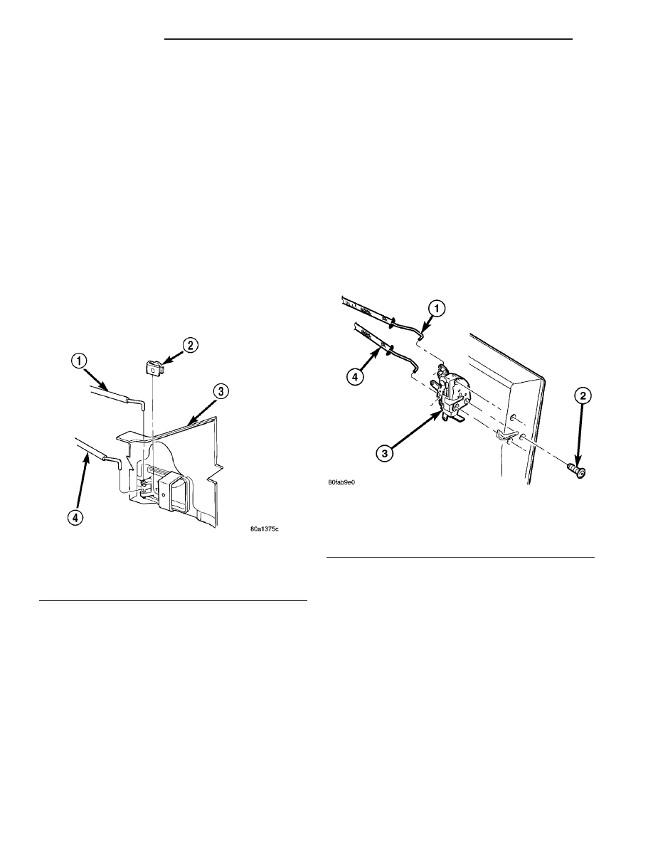
Fig. 11 DOOR LATCH ASSEMBLY

1 - RELEASE ROD
2 - SCREWS (3)
3 - LATCH ASSEMBLY
4 - LOCK ROD

23 - 22

FULL DOOR

TJ

HINGE (Continued)

LATCH STRIKER

REMOVAL

(1) Remove the screws attaching the striker to the

body.

(2) Separate the striker and the spacer from the

body (Fig. 12).

INSTALLATION

(1) Position the striker and the spacer on the body.
(2) Install the screws attaching the striker and

spacer to the body.

LOCK CYLINDER

REMOVAL

(1) Remove trim panel. (Refer to 23 - BODY/FULL

DOOR/TRIM PANEL - REMOVAL)

(2) Peel back waterdam.
(3) Disconnect lock cylinder to latch rod.
(4) Remove lock cylinder retaining clip.
(5) Remove the lock cylinder from the door.

INSTALLATION

(1) Install the lock cylinder in the door.
(2) Install lock cylinder retaining clip.
(3) Connect lock cylinder to latch rod.
(4) Secure the waterdam to the door.
(5) Install trim panel. (Refer to 23 - BODY/FULL

DOOR/LOCK CYLINDER - INSTALLATION)

TRIM PANEL

REMOVAL

(1) Lower the window.
(2) Remove the clip attaching the window glass

regulator handle to the regulator. Remove the han-
dle.

(3) Remove the screws attaching trim panel to

door (Fig. 13).

(4) Using a special tool C-4829 or equivalent,

remove push-in fasteners attaching trim panel to
door.

(5) Lift the trim panel upward and separate the

trim panel from the door.

INSTALLATION

(1) Position the trim panel on the door.
(2) Press the push-in fasteners attaching trim

panel to door into place.

(3) Install the screws attaching trim panel to door.
(4) Position the clip on regulator handle and

install the handle on the regulator.

Fig. 12 LATCH STRIKER

1 - STRIKER
2 - SPACER
3 - BODY

Fig. 13 FULL

1 - FULL DOOR
2 - GRAB HANDLE BRACKET
3 - TRIM PANEL
4 - NUT

TJ

FULL DOOR

23 - 23

HALF DOOR

TABLE OF CONTENTS

page

page

DOOR

REMOVAL

. . . . . . . . . . . . . . . . . . . . . . . . . . . . . 24

INSTALLATION

. . . . . . . . . . . . . . . . . . . . . . . . . 24

WINDOW

REMOVAL

. . . . . . . . . . . . . . . . . . . . . . . . . . . . . 24

INSTALLATION

. . . . . . . . . . . . . . . . . . . . . . . . . 24

EXTERIOR HANDLE

REMOVAL

. . . . . . . . . . . . . . . . . . . . . . . . . . . . . 25

INSTALLATION

. . . . . . . . . . . . . . . . . . . . . . . . . 25

HINGE

DESCRIPTION

. . . . . . . . . . . . . . . . . . . . . . . . . 25

INSIDE HANDLE ACTUATOR

REMOVAL

. . . . . . . . . . . . . . . . . . . . . . . . . . . . . 25

INSTALLATION

. . . . . . . . . . . . . . . . . . . . . . . . . 25

LATCH

REMOVAL

. . . . . . . . . . . . . . . . . . . . . . . . . . . . . 25

INSTALLATION

. . . . . . . . . . . . . . . . . . . . . . . . . 26

LATCH STRIKER

REMOVAL

. . . . . . . . . . . . . . . . . . . . . . . . . . . . . 26

INSTALLATION

. . . . . . . . . . . . . . . . . . . . . . . . . 26

LOCK CYLINDER

REMOVAL

. . . . . . . . . . . . . . . . . . . . . . . . . . . . . 26

INSTALLATION

. . . . . . . . . . . . . . . . . . . . . . . . . 26

TRIM PANEL

REMOVAL

. . . . . . . . . . . . . . . . . . . . . . . . . . . . . 26

INSTALLATION

. . . . . . . . . . . . . . . . . . . . . . . . . 26

DOOR

REMOVAL

(1) Open the door.
(2) Disconnect the door restraint strap from the

pin (Fig. 1).

(3) Remove the nuts at the door hinge pivots and

lift the door from the body.

INSTALLATION

(1) Position the door in the hinge and install the

nuts.

(2) Connect the door restraint strap at the pin.
(3) Check for proper operation.

WINDOW

REMOVAL

(1) Open the door.
(2) Grasp the window at both front and rear edges

and firmly lift upward (Fig. 2).

INSTALLATION

(1) Starting at the most forward alignment pin,

position the window alignment pins into the restraint
sleeves and push downward until seated.

Fig. 1 RESTRAINT STRAP

1 - BODY
2 - FOOTMAN LOOP
3 - STRAP
4 - RESTRAINT PIN

Fig. 2 HALF WINDOW

23 - 24

HALF DOOR

TJ

EXTERIOR HANDLE

REMOVAL

(1) Remove trim panel. (Refer to 23 - BODY/HALF

DOOR/TRIM PANEL - REMOVAL)

(2) Disconnect the outside handle to latch rod.
(3) Remove screws attaching the outside handle to

the door.

(4) Separate the outside handle and seal from the

door.

INSTALLATION

(1) Position the outside handle and seal in the

door.

(2) Install screws attaching the outside handle to

the door.

(3) Connect the outside handle to latch rod.
(4) Install trim panel. (Refer to 23 - BODY/HALF

DOOR/TRIM PANEL - INSTALLATION)

HINGE

DESCRIPTION

The service procedures for the half door hinge are

the same as the full door hinge. (Refer to 23 - BODY/
FULL DOOR/HINGE - REMOVAL) and (Refer to 23 -
BODY/FULL DOOR/HINGE - INSTALLATION).

INSIDE HANDLE ACTUATOR

REMOVAL

(1) Remove the torx screw attaching the inside

handle to the door.

(2) Carefully pull handle from door.
(3) Disconnect the latch rods from the handle (Fig.

3).

INSTALLATION

(1) Connect the latch rods to the handle.
(2) Position handle and seal in door.
(3) Install the torx screw attaching the inside han-

dle the to door.

LATCH

REMOVAL

(1) Remove trim panel. (Refer to 23 - BODY/HALF

DOOR/TRIM PANEL - REMOVAL)

(2) Disconnect the lock cylinder to latch rod (Fig.

4).

(3) Disconnect the lock knob to latch rod.
(4) Disconnect the outside handle to latch rod.

(5) Using a trim stick or equivalent, pry back the

door weatherstrip at the latch to access the screw
attaching the latch to the door.

(6) Remove the screws attaching the latch to the

door (Fig. 5).

(7) Lower the latch in the door and disconnect the

inside handle to latch rod.

(8) Remove the latch from the door.

Fig. 3 INSIDE HANDLE ACTUATOR

1 - LOCK KNOB TO LATCH ROD
2 - U-NUT
3 - HALF DOOR TRIM PANEL
4 - INSIDE RELEASE HANDLE TO LATCH ROD

Fig. 4 HALF DOOR LATCH RODS

1 - LOCK CYLINDER
2 - HALF DOOR
3 - HALF DOOR
4 - LATCH
5 - LOCK CYLINDER TO LATCH ROD
6 - LOCK CYLINDER
7 - RETAINER
8 - OUTSIDE HANDLE
9 - INSIDE HANDLE TO LATCH ROD
10 - INSIDE LOCK TO LATCH ROD

TJ

HALF DOOR

23 - 25


Content   ..  543  544  545  546   ..