Jeep Wrangler TJ. Manual - part 529


  Index      Jeep     Jeep Wrangler TJ - service repair manual 2005 year


Search            


Content   ..  527  528  529  530   ..


Jeep Wrangler TJ. Manual - part 529


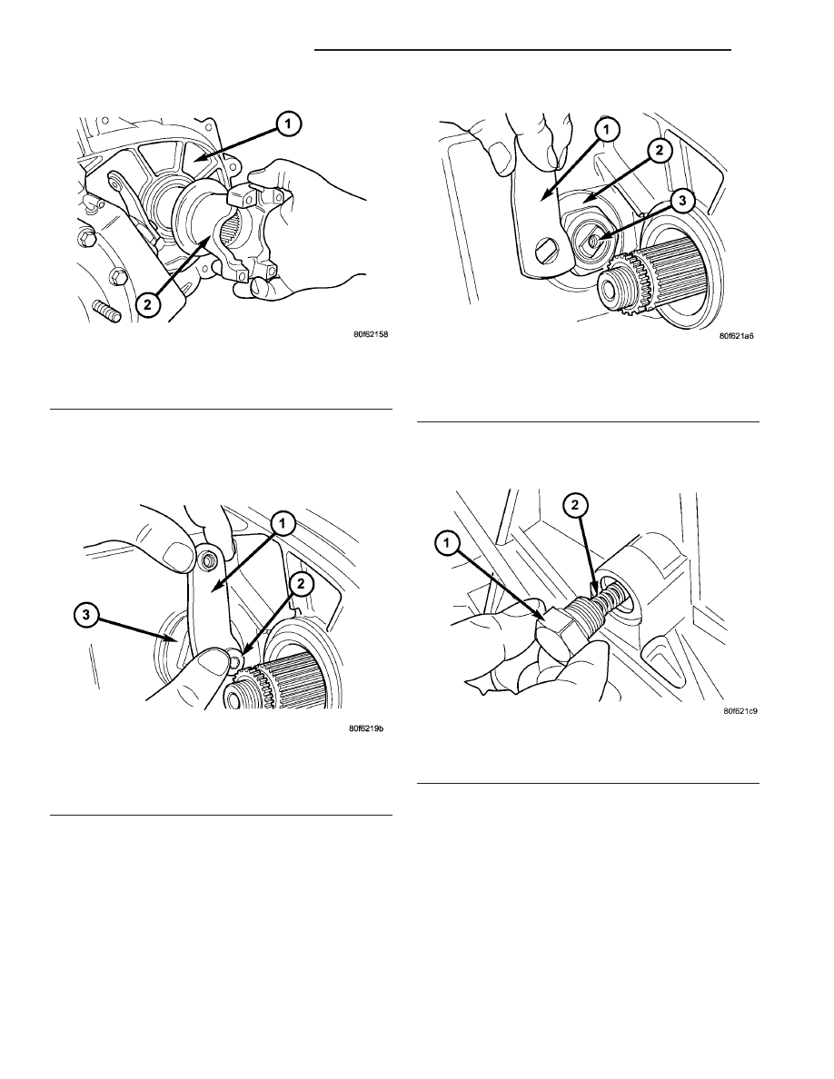
(6) Remove bolt (Fig. 12) that retains the shift

lever to sector shaft.

(7) Remove the shift lever (Fig. 13) from the shift

sector.

(8) Remove the detent plug (Fig. 14).

Fig. 14 Detent Plug Removal

1 - DETENT PLUG
2 - SPRING

Fig. 11 Front Yoke Removal

1 - TRANSFER CASE
2 - FRONT YOKE

Fig. 12 Shift Lever Bolt Removal

1 - SHIFT LEVER
2 - BOLT
3 - SECTOR SUPPORT

Fig. 13 Shift Lever Removal

1 - SHIFT LEVER
2 - SECTOR SUPPORT
3 - SHIFT SECTOR

21 - 206

TRANSFER CASE - NV241

TJ

TRANSFER CASE - NV241 (Continued)

(9) Remove the detent plug (Fig. 15), spring, and

plunger from the transfer case.

(10) Remove the transfer case position sensor (Fig.

16).

(11) Remove the shift sector support (Fig. 17).

MAINSHAFT, FRONT OUTPUT SHAFT, AND DRIVE
CHAIN

(1) Note position of bolts that attach rear case to

front case. Some bolts are unique. Mark position of
these bolts with paint or scriber.

(2) Remove rear case-to-front case bolts (Fig. 18).

(3) Loosen rear case with pry tool to break sealer

bead.

Fig. 15 Detent Plug, Spring, and Plunger Removal

1 - DETENT PLUG
2 - SPRING
3 - PLUNGER

Fig. 16 Remove Transfer Case Position Sensor

1 - TRANSFER CASE POSITION SENSOR
2 - TRANSFER CASE

Fig. 17 Shift Sector Support Removal

1 - SHIFT SECTOR SHAFT
2 - SECTOR SUPPORT

Fig. 18 Case Half Bolt Removal

1 - REAR CASE HALF
2 - FRONT CASE HALF
3 - BOLTS

TJ

TRANSFER CASE - NV241

21 - 207

TRANSFER CASE - NV241 (Continued)

(4) Unseat rear case from alignment dowels (Fig.

19).

(5) Remove rear case and oil pump assembly from

front case (Fig. 20).

CAUTION: Do not remove the bolts holding the oil
pump cover to the rear case half. The oil pump
cover is aligned to the rear output shaft bearing
inner race and will become mis-aligned if the bolts
are loosened. If the transfer case failure has gener-
ated any debris which may have become trapped in
the oil pump, the rear case and oil pump assembly
MUST be replaced.

(6) Remove shift rail cups and spring (Fig. 21).

(7) Remove front drive sprocket retaining ring

(Fig. 22).

Fig. 19 Case Alignment Dowel

1 - REAR CASE HALF
2 - FRONT CASE HALF
3 - ALIGNMENT DOWEL

Fig. 20 Rear Case Half Removal

1 - REAR CASE HALF
2 - FRONT CASE HALF

Fig. 21 Shift Rail Cup And Spring Removal

1 - SHIFT RAIL
2 - SPRING
3 - CUPS (2)

Fig. 22 Front Drive Sprocket Snap-Ring Removal

1 - DRIVE CHAIN
2 - FRONT DRIVE SPROCKET
3 - SNAP-RING

21 - 208

TRANSFER CASE - NV241

TJ

TRANSFER CASE - NV241 (Continued)

(8) Remove mainshaft, front sprocket, and chain as

an assembly (Fig. 23).

SHIFT FORKS

(1) Remove front output shaft from bearing in case

(Fig. 24).

(2) Remove the shift rail (Fig. 25) from the shift

forks.

(3) Remove mode fork, mode sleeve (Fig. 26). Note

which way sleeve fits in fork (long side of sleeve goes
to front).

Fig. 23 Remove Mainshaft, Drive Chain, and Front

Sprocket

1 - MAINSHAFT
2 - DRIVE CHAIN
3 - DRIVE SPROCKET

Fig. 24 Front Output Shaft Removal

1 - FRONT CASE HALF
2 - FRONT OUTPUT SHAFT

Fig. 25 Shift Fork Rail Removal

1 - FRONT CASE HALF
2 - SHIFT RAIL

Fig. 26 Mode Fork and Sleeve Removal

1 - MODE FORK
2 - MODE SLEEVE

TJ

TRANSFER CASE - NV241

21 - 209

TRANSFER CASE - NV241 (Continued)


Content   ..  527  528  529  530   ..