Jeep Wrangler TJ. Manual - part 519


  Index      Jeep     Jeep Wrangler TJ - service repair manual 2005 year


Search            


Content   ..  517  518  519  520   ..


Jeep Wrangler TJ. Manual - part 519


IDENTIFICATION

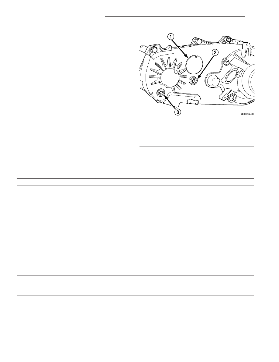
A circular ID tag is attached to the rear case of

each transfer case (Fig. 1). The ID tag provides the
transfer case model number, assembly number, serial
number, and low range ratio.

The transfer case serial number also represents

the date of build.

OPERATION

The input gear is splined to the transmission out-

put shaft. The input gear drives the mainshaft
through the planetary assembly and range hub. The
front output shaft is operated by a drive chain that
connects the shaft to a drive sprocket on the main-
shaft. The drive sprocket is engaged/disengaged by
the mode fork, which operates the mode sleeve and
hub. The sleeve and hub are not equipped with a
synchronizer mechanism for shifting.

DIAGNOSIS AND TESTING - TRANSFER CASE - NV231

DIAGNOSIS CHART

Condition

Possible Cause

Correction

Transfer case difficult to shift or will
not shift into desired range.

1) Vehicle speed to great to permit
shifting.

1) Slow vehicle and shift into
desired range.

2) If vehicle was operated for an
extended period in 4H mode on dry
surface, driveline torque load may
cause difficulty.

2) Stop vehicle and shift transfer
case to Neutral position. Transfer
case can then be shifted to the
desired mode.

3) Transfer case shift linkage
binding.

3) Repair or replace linkage as
necessary.

4) Insufficient or incorrect lubricant.

4) Drain and refill transfer case with
the correct type and quantity of
lubricant.

5) Internal transfer case
components binding, worn, or
damaged.

5) Repair or replace components as
necessary.

Transfer case noisy in all drive
modes.

1) Insufficient or incorrect lubricant.

1) Drain and refill transfer case with
the correct type and quantity of
lubricant.

Fig. 1 Fill/Drain Plug And I.D. Tag Locations -

Typical

1 - I.D. TAG
2 - FILL PLUG
3 - DRAIN PLUG

21 - 166

TRANSFER CASE - NV231

TJ

TRANSFER CASE - NV231 (Continued)

Condition

Possible Cause

Correction

Transfer case noisy while in, or
jumps out of, 4L mode.

1) Transfer case not completely
engaged in 4L position.

1) Slow vehicle, shift transfer case
to the Neutral position, and then
shift into the 4L mode.

2) Transfer case shift linkage out of
adjustment.

2) Adjust linkage as necessary.

3) Transfer case shift linkage loose
or binding.

3) Repair, replace, or tighten linkage
components as necessary.

4) Range fork damaged, inserts
worn, or fork is binding on the shift
rail.

4) Repair or replace components as
necessary.

5) Low range gear worn or
damaged.

5) Repair or replace components as
necessary.

Lubricant leaking from transfer case
seals or vent.

1) Transfer case overfilled.

1) Drain lubricant to the correct
level.

2) Transfer case vent closed or
restricted.

2) Clean or replace vent as
necessary.

3) Transfer case seals damaged or
installed incorrectly.

3) Replace suspect seal.

Abnormal tire wear.

1) Extended operation in 4H mode
on dry surfaces,

1) Operate vehicle in 2H mode on
dry surfaces.

REMOVAL

(1) Shift transfer case into NEUTRAL.
(2) Raise vehicle.
(3) Drain transfer case lubricant.
(4) Mark front and rear propeller shaft yokes for

alignment reference.

(5) Support transmission with jack stand.
(6) Remove rear crossmember, or skid plate.
(7) Disconnect front/rear propeller shafts at trans-

fer case.

(8) Disconnect vehicle speed sensor wires.
(9) Disconnect transfer case linkage rod from

range lever.

(10) Disconnect transfer case vent hose (Fig. 2)

and indicator switch harness, if necessary.

(11) Support transfer case with transmission jack.
(12) Secure transfer case to jack with chains.
(13) Remove nuts attaching transfer case to trans-

mission.

(14) Pull transfer case and jack rearward to disen-

gage transfer case.

(15) Remove transfer case from under vehicle.

DISASSEMBLY

Position transfer case on shallow drain pan.

Remove drain plug and drain lubricant remaining in
case.

REAR RETAINER AND OIL PUMP

(1) Remove the speedometer adapter.
(2) Spread band clamp which holds output shaft

boot to the output shaft slinger, or output shaft
damper, with a suitable awl, or equivalent.

Fig. 2 Transfer Case Mounting

1 - VENT TUBE
2 - TRANSFER CASE
3 - TRANSMISSION

TJ

TRANSFER CASE - NV231

21 - 167

TRANSFER CASE - NV231 (Continued)

NOTE: Vehicles built with a 4.0L engine and a man-
ual transmission use a damper weight on the trans-
fer case output shaft. Be sure to identify the
transfer case before proceeding.

(3) Remove output shaft boot from slinger, or out-

put shaft damper, and output shaft.

(4) If the vehicle is not equipped with an output

shaft damper, remove the output shaft rear slinger
using Puller MD-998056-A (Fig. 3).

(5) If the vehicle is equipped with an output shaft

damper, use Screws 8421 and the puller yoke and
forcing screw from a bolt-grip puller set, such as
those used to remove steering wheels and harmonic
balancers, to remove the transfer case output shaft
damper.

(6) Use a suitable pry tool, or a slide hammer

mounted screw, to remove the seal from the rear
retainer (Fig. 4).

(7) Remove the rear output bearing I.D. retaining

ring (Fig. 5).

(8) Remove the bolts holding the rear retainer to

the rear case half.

(9) Tap rear retainer with rawhide or rubber mal-

let to loosen sealer bead.

(10) Remove rear retainer from rear case half (Fig.

6).

Fig. 3 Rear Slinger Removal

1 - TRANSFER CASE
2 - SPECIAL TOOL MD-998056-A
3 - SLINGER

Fig. 4 Rear Retainer Seal

1 - REAR RETAINER
2 - OUTPUT SHAFT SEAL

Fig. 5 Output Shaft Rear Bearing Retaining Ring

1 - SNAP-RING PLIERS
2 - REAR BEARING I.D. RETAINING RING

Fig. 6 Rear Retainer Removal

1 - MAINSHAFT
2 - REAR RETAINER

21 - 168

TRANSFER CASE - NV231

TJ

TRANSFER CASE - NV231 (Continued)

(11) Remove snap-ring holding oil pump in position

on output shaft.

(12) Disengage oil pickup tube from oil pump and

remove oil pump assembly. Remove oil pump by tilt-
ing the edge of the oil pump from under the edge of
the rear case half and sliding the pump (Fig. 7).

(13) Remove pick-up tube o-ring from oil pump

(Fig. 8), if necessary. Do not disassemble the oil
pump, it is not serviceable.

YOKE AND RANGE LEVER

(1) Remove transfer case indicator switch.
(2) Remove front yoke nut as follows:

(a) Move range lever to 4L position.
(b) Then remove nut with socket and impact

wrench (Fig. 9).

(3) Remove yoke. If yoke is difficult to remove by

hand, remove it with bearing splitter, or with stan-
dard two jaw puller (Fig. 10). Be sure puller tool is
positioned on yoke and not on slinger as slinger will
be damaged.

(4) Remove seal washer from front output shaft.

Discard washer as it should not be reused.

Fig. 7 Oil Pump Removal

1 - OIL PUMP

Fig. 8 Pick-up Tube O-ring Location

1 - OIL PUMP
2 - O-RING

Fig. 9 Yoke Nut Removal

1 - IMPACT WRENCH
2 - SOCKET
3 - YOKE

Fig. 10 Yoke Removal

1 - PULLER TOOL
2 - YOKE

TJ

TRANSFER CASE - NV231

21 - 169

TRANSFER CASE - NV231 (Continued)


Content   ..  517  518  519  520   ..