Jeep Wrangler TJ. Manual - part 497


  Index      Jeep     Jeep Wrangler TJ - service repair manual 2005 year


Search            


Content   ..  495  496  497  498   ..


Jeep Wrangler TJ. Manual - part 497


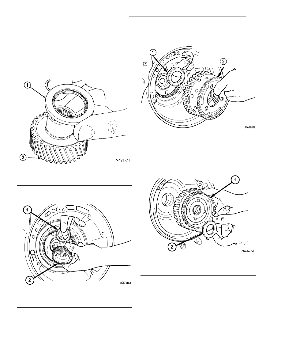
(26) Install the #7 needle bearing to the rear sun

gear (Fig. 112). The number 7 needle bearing has
three antireversal tabs and is common with the
number 5 and number 2 position. The orienta-
tion should allow the bearing to seat flat
against the rear sun gear. A small amount of
petrolatum can be used to hold the bearing to
the rear sun gear.

(27) Install rear sun gear and #7 needle bearing

(Fig. 113).

(28) Install front carrier/rear annulus assembly

and #6 needle bearing (Fig. 114).

(29) Install front sun gear assembly and #4 thrust

washer (Fig. 115).

Fig. 112 Number 7 Bearing

1 - #7 BEARING
2 - REAR SUN GEAR

Fig. 113 Install Rear Sun Gear

1 - #7 NEEDLE BEARING
2 - REAR SUN GEAR

Fig. 114 Install Front Carrier/Rear Annulus

1 - #6 NEEDLE BEARING
2 - FRONT CARRIER AND REAR ANNULUS ASSEMBLY (TWIST
AND PULL OR PUSH TO REMOVE OR INSTALL).

Fig. 115 Install Front Sun Gear Assembly

1 - FRONT SUN GEAR ASSEMBLY
2 - #4 THRUST WASHER (FOUR TABS)

21 - 78

AUTOMATIC TRANSMISSION - 42RLE

TJ

AUTOMATIC TRANSMISSION - 42RLE (Continued)

(30) Determine proper #4 thrust plate thick-

ness.

(a) Select the thinnest #4 thrust plate thickness.
(b) Install #4 thrust plate (Fig. 116) using petro-

latum to hold into position.

(c) Install input clutch assembly. Ensure the

input clutch assembly is completely seated by view-
ing position through input speed sensor hole. If
the speed sensor tone wheel is not centered
in the opening, the input clutch assembly is
not seated properly.

(d) Remove the oil pump o-ring (Fig. 117) and

install oil pump and gasket to transmission.
Tighten the oil pump bolts to 30 N·m (265 in. lbs.).
Use screw-in dowels or phillips-head screw-
drivers to align pump to case. Be sure to rein-
stall O-ring on oil pump after selecting the
proper No. 4 thrust plate.

(e) Measure the input shaft end play with the

transmission in the vertical position. This will
ensure that the measurement will be accurate.

(f) Set up and measure endplay using End Play

Set 8266 and Dial Indicator Set C3339 as shown in
(Fig. 118).

(g) Measure input shaft end play. Input shaft

end play must be 0.127 to 0.635 mm (0.005 to
0.025 inch). 
For example, if end play reading is
0.055 inch, select No. 4 Thrust Plate which is 0.071
to 0.074 thick. This should provide an input shaft
end play reading of 0.020 inch, which is within
specifications.

(h) Remove oil pump, gasket, and input clutch

assembly to gain access to and install proper #4
thrust plate.

Fig. 116 Install #4 Thrust Plate

1 - OVERDRIVE SHAFT ASSEMBLY
2 - #4 THRUST PLATE (SELECT)
3 - PETROLATUM FOR RETENTION

Fig. 117 Remove Oil Pump O-Ring

1 - OIL PUMP ASSEMBLY
2 - O-RING

Fig. 118 Measure Input Shaft End Play Using Tool

8266 - Typical

1 - TOOL 8266-8
2 - TOOL 8266-2
3 - TOOL C-3339

TJ

AUTOMATIC TRANSMISSION - 42RLE

21 - 79

AUTOMATIC TRANSMISSION - 42RLE (Continued)

(31) Install input clutch assembly with proper

thrust plate (Fig. 119).

(32) Install #1 caged needle bearing (Fig. 120).

(33) Replace cooler by-pass valve if transmission

failure has occurred (Fig. 121).

CAUTION: By-pass valve MUST be replaced if trans-
mission failure occurs.

NOTE: To align oil pump, gasket, and case during
installation, use threaded dowels or phillips screw-
drivers.

(34) Install oil pump gasket (Fig. 122).

Fig. 119 Install Input Clutch Assembly

1 - INPUT CLUTCH ASSEMBLY

Fig. 120 Install No. 1 Caged Needle Bearing

1 - #1 CAGED NEEDLE BEARING
2 - NOTE: TANGED SIDE OUT

Fig. 121 Install By-Pass Valve

1 - BYPASS VALVE

Fig. 122 Install Oil Pump Gasket

1 - BELLHOUSING
2 - OIL PUMP GASKET

21 - 80

AUTOMATIC TRANSMISSION - 42RLE

TJ

AUTOMATIC TRANSMISSION - 42RLE (Continued)

(35) Install oil pump and torque the new oil pump-

to-case bolts to 30 N·m (265 in. lbs.) (Fig. 123). Do
not reuse original oil pump bolts.

(36) Install low/reverse accumulator as shown in

(Fig. 124).

(37) Install low/reverse accumulator plug (Fig.

125).

(38) Install low/reverse accumulator snap ring

(Fig. 126).

Fig. 123 Install Oil Pump Attaching Bolts

1 - BOLTS
2 - OIL PUMP

Fig. 124 Low/Reverse Accumulator

1 - PISTON
2 - RETURN SPRINGS

Fig. 125 Install Low/Reverse Accumulator Plug

1 - ADJUSTABLE PLIERS
2 - PLUG

Fig. 126 Install Low/Reverse Accumulator Snap

Ring

1 - SNAP RING
2 - LOW/REVERSE ACCUMULATOR

TJ

AUTOMATIC TRANSMISSION - 42RLE

21 - 81

AUTOMATIC TRANSMISSION - 42RLE (Continued)


Content   ..  495  496  497  498   ..