Jeep Wrangler TJ. Manual - part 485


  Index      Jeep     Jeep Wrangler TJ - service repair manual 2005 year


Search            


Content   ..  483  484  485  486   ..


Jeep Wrangler TJ. Manual - part 485


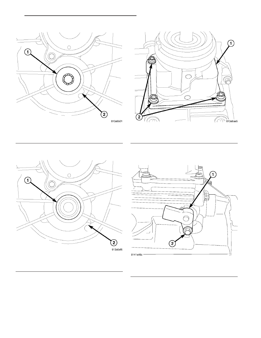
(17) Install countershaft bolt (1) (Fig. 114) into the

front housing (2) and tighten to 100 N·m (74 ft. lbs.).

(18) Install countershaft plug (1) (Fig. 115) in front

housing (2) with Installer 7829-A and Handle C-4171.

(19) Move shift rails to neutral.

(20) Apply MOPAR

t Gasket Maker to shift tower.

(21) Install shift tower (1) (Fig. 116) and tighten

bolts (2) to 14 N·m (10 ft. lbs.).

(22) Install back up lamp switch (1) and bolt (2)

(Fig. 117).

Fig. 114 COUNTERSHAFT BOLT

1 - COUNTERSHAFT BOLT
2 - FRONT HOUSING

Fig. 115 COUNTERSHAFT PLUG

1 - COUNTERSHAFT PLUG
2 - FRONT HOUSING

Fig. 116 SHIFT TOWER

1 - SHIFT TOWER
2 - BOLTS

Fig. 117 BACK-UP LAMP SWITCH

1 - SWITCH
2 - BOLTS

TJ

MANUAL TRANSMISSION - NSG370

21 - 31

MANUAL TRANSMISSION - NSG370 (Continued)

INSTALLATION

(1) Install transmission on engine.
(2) On 2.4L engine tighten bolts (1) to 75 N·m (55

ft. lbs.). Install lower dust shield and tighten bolts (2)
to 34 N·m (25 ft. lbs.) (Fig. 118).

(3) On 4.0L engine tighten bolts (1) to 37 N·m (27

ft. lbs.). Install side and lower dust shield and
tighten bolts (2) (3) to 58 N·m (43 ft. lbs.) (Fig. 119).

(4) Clean shift tower and mating surface then

apply Mopar

t Gasket Maker to shift tower.

(5) Install shift tower (2) and tighten bolts (1) to

10 N·m (7 ft. lbs.) (Fig. 120).

(6) Install backup lamp (2) wiring connector (1)

(Fig. 121).

(7) Install clutch slave cylinder (2) and mounting

nuts (1) (Fig. 122).

(8) Install catalyst assembly (2) on 2.4L engine

(Fig. 123).

Fig. 118 2.4L ENGINE

1. TRANSMISSION BOLT
2. DUST SHIELD BOLT

Fig. 119 4.0L ENGINE

1. UPPER TRANSMISSION BOLTS
2. SIDE DUST COVER BOLTS
3. LOWER DUST COVER BOLTS

Fig. 120 SHIFT LEVER

1. BOLTS
2. SHIFT TOWER

Fig. 121 BACKUP LAMP SWITCH

1. CONNECTOR
2. BACKUP LAMP SWITCH

21 - 32

MANUAL TRANSMISSION - NSG370

TJ

MANUAL TRANSMISSION - NSG370 (Continued)

2005 TJ Service Manual
Publication No. 81-370-05063
05TJ21-32

September, 2004

(9) Install transmission crossmember and tighten

bolts to 47 N·m (35 ft. lbs.). Install transmission
mount bolts and tighten to 47 N·m (35 ft. lbs.).

(10) Install transfer case, if equipped.
(11) Install transfer case shift linkage.

(12) Install transfer case wiring connector and

vent hose.

(13) Install propeller shaft/shafts with reference

marks aligned.

(14) Remove fill plug (1) and fill transmission

withn lubricant (Fig. 124).

Fig. 122 CLUTCH SLAVE CYLINDER

1. BOLTS
2. SLAVE CYLINDER

Fig. 123 2.4L CATALYST ASSEMBLY - 4x4

1- FLANGED NUT
2- CATALYST ASSEMBLY
3- BOLT
4- HANGER
5- NUT

Fig. 124 FILL PLUG

1. FILL PLUG

Fig. 125 ADAPTER OPENING DETAIL

1 - BACK OF ENGINE
2 - ADAPTER PLATE
3- BELLHOUSING - MANUAL TRANSMISSION
4 - ADAPTER PLATE OPENING - APPLY SEALER HERE

TJ

MANUAL TRANSMISSION - NSG370

21 - 33

MANUAL TRANSMISSION - NSG370 (Continued)

2005 TJ Service Manual
Publication No. 81-370-05063
05TJ21-33

September, 2004

(15) Locate narrow adapter plate (2) opening

towards the rear of the engine (1) and top of the
transmission bellhousing (3) from the drivers side of
the engine compartment (Fig. 125).

(16) Thoroughly clean around the adapter opening

(2) with throttle body cleaner and allow cleaner to
dry.

(17) With your finger, apply a sufficient amount of

RTV over the spacer opening (4). Verify that the
adapter (2) opening (4) is completely sealed off by the
RTV (Fig. 126).

Fig. 126 LOCATION OF ADAPTER OPENING

1 - BACK OF ENGINE
2 - LOCATION OF NARROW OPENING DUE TO SLOT IN
ADAPTER PLATE
3 - TOP OF BELLHOUSING - MANUAL TRANSMISSION

21 - 33A

MANUAL TRANSMISSION - NSG370

TJ

MANUAL TRANSMISSION - NSG370 (Continued)

2005 TJ Service Manual
Publication No. 81-370-05063
05TJ21-33A

September, 2004


Content   ..  483  484  485  486   ..