Jeep Wrangler TJ. Manual - part 472


  Index      Jeep     Jeep Wrangler TJ - service repair manual 2005 year


Search            


Content   ..  470  471  472  473   ..


Jeep Wrangler TJ. Manual - part 472


(4) Disconnect the high pressure hose from the

power steering pump.

(5) Connect Tube 6865 to the pump hose fitting.
(6) Connect the power steering hose from the

steering gear to Adapter 6826.

(7) Open the test valve completely.
(8) Start engine and let idle long enough to circu-

late power steering fluid through flow/pressure test
gauge.

(9) Shut off the engine and check the fluid level,

add fluid as necessary. Start engine again and let
idle.

(10) Gauge should read below 862 kPa (125 psi), if

above, inspect the hoses for restrictions and repair as
necessary. The initial pressure reading should be in
the range of 345-552 kPa (50-80 psi).

(11) Increase the engine speed to 1500 RPM and

read the flow meter. The reading should be 2.4 - 2.8
GPM, if the reading is below this specification the
pump should be replaced.

CAUTION: This next step involves testing maximum
pump pressure output and flow control valve oper-
ation. Do not leave test valve closed for more than
three seconds as the pump could be damaged.

(12) Close valve fully three times for three seconds

and record highest pressure indicated each time. All
three readings must be above pump relief pres-
sure specifications and within 345 kPa (50 psi)
of each other.

• Pressures above specifications but not within

345 kPa (50 psi) of each other, replace pump.

• Pressures within 345 kPa (50 psi) of each other

but below specifications, replace pump.

(13) Open the test valve and turn the steering

wheel to the extreme left and right positions against
the stops. Record the highest pressure reading at
each position. Compare readings to pump specifica-
tions chart. If pressure readings are not within 50
psi. of each other, the gear is leaking internally and
must be repaired.

CAUTION: Do not force the pump to operate against
the stops for more than 2 to 4 seconds at a time
because, pump damage will result.

PUMP SPECIFICATIONS

ENGINE

RELIEF

PRESSURE ± 50

FLOW RATE

(GPM)

2.4L

9653 kPa (1400

psi)

1500 RPM 2.4 - 2.8

GPM

4.0L

9653 kPa (1400

psi)

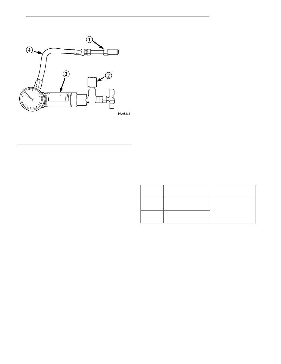
Fig. 4 Power Steering Analyzer

1 - TUBE
2 - ADAPTER FITTINGS
3 - ANALYZER
4 - GAUGE HOSE

TJ

STEERING

19 - 5

STEERING (Continued)

COLUMN

TABLE OF CONTENTS

page

page

COLUMN

DESCRIPTION

. . . . . . . . . . . . . . . . . . . . . . . . . . 6

OPERATION - SERVICE PRECAUTIONS

. . . . . . 6

REMOVAL

. . . . . . . . . . . . . . . . . . . . . . . . . . . . . 6

INSTALLATION

. . . . . . . . . . . . . . . . . . . . . . . . . . 8

SPECIFICATIONS

TORQUE CHART

. . . . . . . . . . . . . . . . . . . . . . 9

IGNITION SWITCH

DESCRIPTION

. . . . . . . . . . . . . . . . . . . . . . . . . . 9

DIAGNOSIS AND TESTING - IGNITION

SWITCH

. . . . . . . . . . . . . . . . . . . . . . . . . . . . . 9

REMOVAL

. . . . . . . . . . . . . . . . . . . . . . . . . . . . . 9

INSTALLATION

. . . . . . . . . . . . . . . . . . . . . . . . . 10

KEY-IN IGNITION SWITCH

DESCRIPTION

. . . . . . . . . . . . . . . . . . . . . . . . . 10

DIAGNOSIS AND TESTING - KEY-IN IGNITION

SWITCH

. . . . . . . . . . . . . . . . . . . . . . . . . . . . 10

KEY CYLINDER

REMOVAL

. . . . . . . . . . . . . . . . . . . . . . . . . . . . . 11

INSTALLATION

. . . . . . . . . . . . . . . . . . . . . . . . . 11

STEERING WHEEL

REMOVAL

. . . . . . . . . . . . . . . . . . . . . . . . . . . . . 11

INSTALLATION

. . . . . . . . . . . . . . . . . . . . . . . . . 12

COLUMN

DESCRIPTION

NOTE: The steering column on vehicles with an
automatic transmission may not be equipped with
an internal locking shaft that allows the ignition key
cylinder to be locked with the key. Alternative meth-
ods of locking the steering wheel for service will
have to be used.

The standard non-tilt and tilt steering column has

been designed to be serviced as an assembly. The col-
umn is connected to the steering gear with an upper
and lower shaft. The lower shaft has a support bear-
ing mounted to a bracket. The bracket mounts to the
frame rail with two bolts. These shafts and bearing
are serviceable. The key cylinder, switches, clock
spring, trim shrouds and steering wheel are serviced
separately.

OPERATION - SERVICE PRECAUTIONS

Safety goggles should be worn at all times when

working on steering columns.

To service the steering wheel, switches or airbag,

refer to Electrical - Restraints and follow all WARN-
INGS and CAUTIONS.

WARNING: THE AIRBAG SYSTEM IS A SENSITIVE,
COMPLEX ELECTRO-MECHANICAL UNIT. BEFORE
ATTEMPTING TO DIAGNOSE, REMOVE OR INSTALL
THE AIRBAG SYSTEM COMPONENTS YOU MUST
FIRST DISCONNECT AND ISOLATE THE BATTERY
NEGATIVE (GROUND) CABLE. THEN WAIT TWO
MINUTES FOR THE SYSTEM CAPACITOR TO DIS-
CHARGE. FAILURE TO DO SO COULD RESULT IN

ACCIDENTAL DEPLOYMENT OF THE AIRBAG AND
POSSIBLE PERSONAL INJURY. THE FASTENERS,
SCREWS, AND BOLTS, ORIGINALLY USED FOR
THE AIRBAG COMPONENTS, HAVE SPECIAL COAT-
INGS AND ARE SPECIFICALLY DESIGNED FOR THE
AIRBAG

SYSTEM.

THEY

MUST

NEVER

BE

REPLACED WITH ANY SUBSTITUTES. ANYTIME A
NEW FASTENER IS NEEDED, REPLACE WITH THE
CORRECT FASTENERS PROVIDED IN THE SERVICE
PACKAGE OR FASTENERS LISTED IN THE PARTS
BOOKS.

REMOVAL

(1) Position front wheels straight ahead.
(2) Remove and isolate the negative ground cable

from the battery.

(3) Remove the airbag, (Refer to 8 - ELECTRICAL/

RESTRAINTS/DRIVER AIRBAG - REMOVAL).

NOTE: If equipped with cruise control, disconnect
clock spring harness from the cruise switch har-
ness on the steering wheel.

(4) Remove the steering wheel with an appropriate

puller (Fig. 1).

NOTE: Ensure the puller jaws are seated in the
pockets (Fig. 2) of the steering wheel armature.

(5) Turn ignition cylinder to the on position and

remove cylinder by pressing release through lower
shroud access hole (Fig. 3) (Refer to 19 - STEERING/
COLUMN/LOCK

CYLINDER

HOUSING

-

REMOVAL).

19 - 6

COLUMN

TJ

(6) Remove knee blocker cover and knee blocker,

(Refer to 23 - BODY/INSTRUMENT PANEL/KNEE
BLOCKER - REMOVAL).

(7) Remove screws from the lower column shroud

(Fig. 4) and remove the shroud.

(8) Remove the steering coupler bolt and column

mounting nuts (Fig. 5) then lower column off the
mounting studs.

(9) Remove upper column shroud (Fig. 4).
(10) Disconnect and remove the wiring harness

from the column (Fig. 6).

NOTE: If vehicle is equipped with automatic trans-
mission, remove shifter interlock cable from the
column. (Refer to 21 - TRANSMISSION/TRANSAXLE/
AUTOMATIC

-

30RH/GEAR

SHIFT

CABLE

-

REMOVAL).

(11) Remove column.

Fig. 1 STEERING WHEEL PULLER

1 - PULLER C-3894-A
2 - STEERING WHEEL

Fig. 2 Steering Wheel Pockets

1 - STEERING WHEEL POCKETS

Fig. 3 LOCK CYLINDER RELEASE

1 - Lower Shroud
2 - Lock Cylinder Release Access Hole
3 - Pin Punch

Fig. 4 SHROUD REMOVAL/INSTALL

1 - Upper Shroud
2 - Lower Shroud

TJ

COLUMN

19 - 7

COLUMN (Continued)

(12) Remove clock spring (Fig. 7), switches, (SKIM

if

equipped)

(Refer

to

8

-

ELECTRICAL/RE-

STRAINTS/CLOCKSPRING - REMOVAL).

INSTALLATION

(1) Align and install column into the steering coupler.
(2) Install column harness and connect harness to

switches.

NOTE: If vehicle is equipped with automatic trans-
mission, install shifter interlock cable. (Refer to 21 -
TRANSMISSION/TRANSAXLE/AUTOMATIC - 30RH/
GEAR SHIFT CABLE - ADJUSTMENTS).

(3) Install the upper column shroud.
(4) Install the column onto the mounting studs.

CAUTION: Lower nuts must be installed and tight-
ened first then the upper nuts in order to prevent
damage to the capsules.

(5) Install the lower mounting nuts and tighten to

17 N·m (150 in. lbs.).

(6) Install the upper mounting nuts and tighten to

17 N·m (150 in. lbs.).

(7) Install the steering column coupler bolt and

tighten to 49 N·m (36 ft. lbs.).

(8) Center the clock spring (if necessary) and

install it on the column, (Refer to 8 - ELECTRICAL/
RESTRAINTS/CLOCKSPRING - INSTALLATION).

(9) Install the lower column shroud and install

mounting screws.

(10) Install the ignition lock cylinder. (Refer to 19 -

STEERING/COLUMN/LOCK CYLINDER HOUSING
- INSTALLATION).

(11) Install the knee blocker and the knee blocker

cover, (Refer to 23 - BODY/INSTRUMENT PANEL/
KNEE BLOCKER - INSTALLATION).

NOTE: Do not reuse the old steering wheel bolt (a
new bolt must be used)

NOTE: If equipped with cruise control, connect
clock spring harness to cruise switch harness on
the steering wheel.

(12) Install the steering wheel and tighten bolt to

54 N·m (40 ft. lbs.).

(13) Install the airbag, (Refer to 8 - ELECTRICAL/

RESTRAINTS/DRIVER AIRBAG - INSTALLATION).

(14) Install the negative battery terminal.

Fig. 5 STEERING COLUMN MOUNTING

1 - Steering Column
2 - Mounting Holes

Fig. 6 WIRING HARNESS COLUMN

1 - Column Wiring Harness
2 - Multi-function Switch
3 - Ignition Switch
4 - Steering Column

Fig. 7 CLOCK SPRING

1 - Tilt Lever
2 - Ignition Switch
3 - Clockspring
4 - Steering Column
5 - SKIM

19 - 8

COLUMN

TJ

COLUMN (Continued)


Content   ..  470  471  472  473   ..