Jeep Wrangler TJ. Manual - part 451


  Index      Jeep     Jeep Wrangler TJ - service repair manual 2005 year


Search            


Content   ..  449  450  451  452   ..


Jeep Wrangler TJ. Manual - part 451


INSTALLATION

The front mounts support the engine at each side.

These supports are made of resilient rubber.

(1) If the engine support bracket was removed,

position the bracket onto the block and install the
attaching bolts (Fig. 74) (Fig. 75). Tighten the bolts
to 50 N·m (37 ft. lbs.) torque.

(2) Place the insulator on the support bracket.

Install

the

insulator

retaining

bolts

and

nuts.

Tighten the bolts and nuts to 40 N·m (30 ft. lbs)
torque.

(3) Install the through bolt and the retaining nut.

Tighten the through bolt nut to 48 N·m (35 ft. lbs.)
torque.

(4) Remove the engine support.
(5) Lower the vehicle.
(6) Connect negative cable to battery.

REAR MOUNT

REMOVAL

A resilient rubber cushion supports the transmis-

sion at the rear between the transmission extension
housing and the rear support crossmember or skid
plate.

ALL TRANSMISSIONS

(1) Disconnect negative cable from battery.
(2) Raise the vehicle and support the transmission.
(3) Remove the nuts holding the support cushion

to the skid plate (Fig. 76) (Fig. 77).

MANUAL TRANSMISSIONS

(1) Remove nuts holding support cushion to trans-

mission support bracket.

(2) Remove the support cushion.
(3) Remove bolts holding transmission support

bracket to transmission.

(4) Remove the transmission support bracket.

AUTOMATIC TRANSMISSIONS

(1) Remove nuts holding support cushion to trans-

mission support bracket (Fig. 77). Remove the sup-
port cushion.

(2) Remove the bolts holding the transmission sup-

port bracket to transmission.

(3) Remove the transmission support bracket.

INSTALLATION

MANUAL TRANSMISSION

(1) Position the transmission mount bracket to the

transmission and install the bolts (Fig. 76).

(2) Tighten the bolts to 54 N·m (40 ft. lbs.) torque.

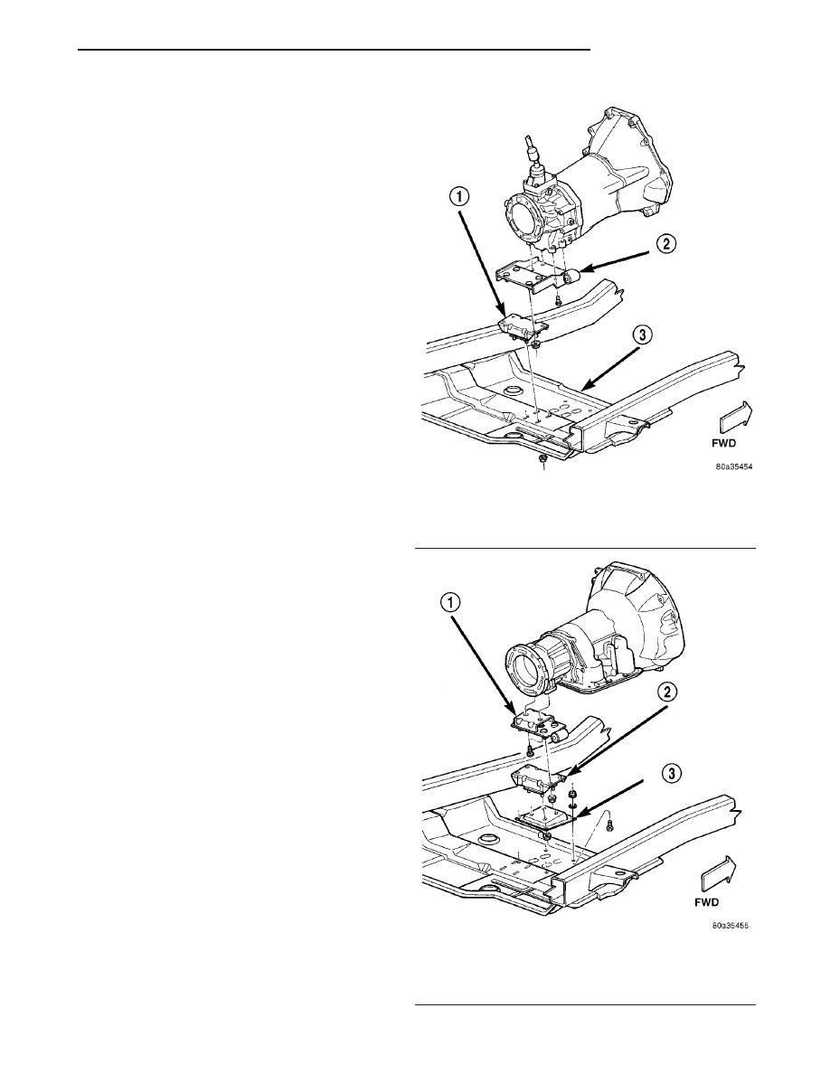
Fig. 76 Rear Mount (Manual Transmission)

1 - CUSHION
2 - BRACKET
3 - SKID PLATE

Fig. 77 Rear Mount (AutomaticTransmission)

1 - BRACKET
2 - CUSHION
3 - BRACKET

TJ

ENGINE 4.0L

9 - 119

FRONT MOUNT (Continued)

(3) Position the support cushion to the transmis-

sion mount bracket and install nuts (Fig. 76).

AUTOMATIC TRANSMISSION

(1) Position the transmission mount bracket to the

transmission and install the bolts. Tighten the bolts
to 54 N·m (40 ft. lbs.) torque.

(2) Position the support cushion to the transmis-

sion mount bracket and install nuts. Tighten the
nuts to 41 N·m (30 ft. lbs.) torque (Fig. 77).

(3) If the support cushion bracket was removed

from the skid plate, position the bracket on the skid
plate and install the nuts and bolts. Tighten the nuts
to 28 N·m (21 ft. lbs.) torque.

ALL TRANSMISSIONS

(1) Position the skid plate to the studs of the sup-

port cushion and install the nuts (Fig. 76) (Fig. 77).
Tighten the nuts to 28 N·m (21 ft. lbs.) torque.

(2) Install the skid plate bolts to the sill and

tighten to 75 N·m (55 ft. lbs.) torque.

(3) Remove the transmission support.
(4) Lower the vehicle.
(5) Connect negative cable to battery.

LUBRICATION

DESCRIPTION

A

gear—type

positive

displacement

pump

is

mounted at the underside of the block opposite the
No. 4 main bearing.

OPERATION

The pump draws oil through the screen and inlet

tube from the sump at the rear of the oil pan. The oil
is driven between the drive and idler gears and
pump body, then forced through the outlet to the
block. An oil gallery in the block channels the oil to
the inlet side of the full flow oil filter. After passing
through the filter element, the oil passes from the
center outlet of the filter through an oil gallery that
channels the oil up to the main gallery which
extends the entire length of the block.

Galleries extend downward from the main oil gal-

lery to the upper shell of each main bearing. The
crankshaft is drilled internally to pass oil from the
main bearing journals (except number 4 main bear-
ing journal) to the connecting rod journals. Each con-
necting rod bearing cap has a small squirt hole, oil
passes through the squirt hole and is thrown off as
the rod rotates. This oil throwoff lubricates the cam-
shaft lobes, distributor drive gear, cylinder walls, and
piston pins.

The hydraulic valve tappets receive oil directly

from the main oil gallery. Oil is provided to the cam-
shaft bearing through galleries. The front camshaft
bearing journal passes oil through the camshaft
sprocket to the timing chain. Oil drains back to the
oil pan under the number one main bearing cap.

The oil supply for the rocker arms and bridged

pivot assemblies is provided by the hydraulic valve
tappets which pass oil through hollow push rods to a
hole in the corresponding rocker arm. Oil from the
rocker arm lubricates the valve train components,
then passes down through the push rod guide holes
in the cylinder head past the valve tappet area, and
returns to the oil pan (Fig. 78).

9 - 120

ENGINE 4.0L

TJ

REAR MOUNT (Continued)

Fig. 78 Oil Lubrication System—4.0L Engine

1 - CAM/CRANK MAIN GALLERY (7)
2 - TAPPET GALLERY
3 - TAPPET GALLERY
4 - CAMSHAFT BEARING

5 - NUMBER 1 CAMSHFT BEARING JOURNAL
6 - CAMSHAFT SPROCKET
7 - TAPPET GALLERY

TJ

ENGINE 4.0L

9 - 121

LUBRICATION (Continued)

DIAGNOSIS AND TESTING

DIAGNOSIS AND TESTING - ENGINE OIL
PRESSURE

(1) Disconnect connector and remove oil pressure

sending unit.

(2) Install Oil Pressure Line and Gauge Tool

C-3292 or equivalent. Start engine and record pres-
sure. (Refer to 9 - ENGINE - SPECIFICATIONS) for
the correct pressures.

DIAGNOSIS AND TESTING - ENGINE OIL LEAK

Begin with a thorough visual inspection of the

engine, particularly at the area of the suspected leak.
If an oil leak source is not readily identifiable, the
following steps should be followed:

(1) Do not clean or degrease the engine at this

time because some solvents may cause rubber to
swell, temporarily stopping the leak.

(2) Add an oil soluble dye (use as recommended by

manufacturer). Start the engine and let idle for
approximately 15 minutes. Check the oil dipstick to
make sure the dye is thoroughly mixed as indicated
with a bright yellow color under a black light.

(3) Using a black light, inspect the entire engine

for fluorescent dye, particularly at the suspected area
of oil leak. If the oil leak is found and identified,
repair per service manual instructions.

(4) If dye is not observed, drive the vehicle at var-

ious speeds for approximately 24km (15 miles), and
repeat inspection.If the oil leak source is not pos-
itively identified at this time
, proceed with the air
leak detection test method.

Air Leak Detection Test Method

(1) Disconnect the breather cap to air cleaner hose

at the breather cap end. Cap or plug breather cap
nipple.

(2) Remove the CCV valve from the cylinder head

cover. Cap or plug the CCV valve grommet.

(3) Attach an air hose with pressure gauge and

regulator to the dipstick tube.

CAUTION: Do not subject the engine assembly to
more than 20.6 kpa (3 PSI) of test pressure.

(4) Gradually apply air pressure from 1 psi to 2.5

psi maximum while applying soapy water at the sus-
pected source. Adjust the regulator to the suitable
test pressure that provide the best bubbles which
will pinpoint the leak source. If the oil leak is
detected and identified, repair per service informa-
tion procedures.

(5) If the leakage occurs at the rear oil seal area,

INSPECTION FOR REAR SEAL AREA LEAKS.

(6) If no leaks are detected, turn off the air supply

and remove the air hose and all plugs and caps.
Install the CCV valve and breather cap hose.

(7) Clean the oil off the suspect oil leak area using

a suitable solvent. Drive the vehicle at various
speeds approximately 24 km (15 miles). Inspect the
engine for signs of an oil leak by using a black light.

INSPECTION FOR REAR SEAL AREA LEAKS

Since it is sometimes difficult to determine the

source of an oil leak in the rear seal area of the
engine, a more involved inspection is necessary. The
following steps should be followed to help pinpoint
the source of the leak.

If the leakage occurs at the crankshaft rear oil seal

area:

(1) Disconnect the battery.
(2) Raise the vehicle.
(3) Remove torque converter or clutch housing

cover and inspect rear of block for evidence of oil.
Use a black light to check for the oil leak:

(a) Circular spray pattern generally indicates

seal leakage or crankshaft damage.

(b) Where leakage tends to run straight down,

possible causes are a porous block, distributor seal,
camshaft bore cup plugs oil galley pipe plugs, oil
filter runoff, and main bearing cap to cylinder
block mating surfaces.
(4) If no leaks are detected, pressurize the crank-

case as outlined in the, Inspection (Engine oil Leaks
in general)

CAUTION: Do not exceed 20.6 kPa (3 psi).

(5) If the leak is not detected, very slowly turn the

crankshaft and watch for leakage. If a leak is
detected between the crankshaft and seal while
slowly turning the crankshaft, it is possible the
crankshaft seal surface is damaged. The seal area on
the crankshaft could have minor nicks or scratches
that can be polished out with emery cloth.

CAUTION: Use extreme caution when crankshaft
polishing is necessary to remove minor nicks and
scratches. The crankshaft seal flange is especially
machined to complement the function of the rear oil
seal.

(6) For bubbles that remain steady with shaft

rotation, no further inspection can be done until dis-
assembled.

9 - 122

ENGINE 4.0L

TJ

LUBRICATION (Continued)


Content   ..  449  450  451  452   ..