Jeep Wrangler TJ. Manual - part 449


  Index      Jeep     Jeep Wrangler TJ - service repair manual 2005 year


Search            


Content   ..  447  448  449  450   ..


Jeep Wrangler TJ. Manual - part 449


(7) Slowly swing the weighted arm onto the push

rod.

(8) Rotate the cup by turning the handle at the

base of the tester clockwise one revolution every 2
seconds.

(9) Observe the leak-down time interval from the

instant the pointer aligns with the START mark on
the scale until the pointer aligns with the 0.125
mark. A normally functioning tappet will require
20-110 seconds to leak-down. Discard tappets with
leak-down time interval not within this specification.

INSTALLATION

Retain all the components in the same order as

removed.

It is not necessary to charge the tappets with

engine oil. They will charge themselves within a very
short period of engine operation.

(1) Dip each tappet in Mopar

t Engine Oil Supple-

ment, or equivalent.

(2) Use Hydraulic Valve Tappet Removal/Installa-

tion Tool to install each tappet in the same bore from
where it was originally removed.

(3) Install the cylinder head (Refer to 9 - ENGINE/

CYLINDER HEAD - INSTALLATION).

(4) Install the push rods in their original locations.
(5) Install the rocker arms and bridge and pivot

assemblies at their original locations. Loosely install
the capscrews at each bridge.

(6) Tighten the capscrews alternately, one turn at

a time, to avoid damaging the bridges. Tighten the
capscrews to 28 N·m (21 ft. lbs.) torque.

(7) Pour the remaining Mopar

t Engine Oil Supple-

ment, or equivalent over the entire valve actuating
assembly. The Mopar

t Engine Oil Supplement, or

equivalent must remain with the engine oil for at
least 1 609 km (1,000 miles). The oil supplement
need not be drained until the next scheduled oil
change.

(8) Install the cylinder head cover (Refer to 9 -

ENGINE/CYLINDER

HEAD/CYLINDER

HEAD

COVER(S) - INSTALLATION).

PISTON & CONNECTING ROD

DESCRIPTION

The pistons (Fig. 56) are made of a high strength

aluminum alloy, the piston skirts are coated with a
solid lubricant (Molykote) to reduce friction and pro-
vide scuff resistance. The connecting rods are made
of cast iron.

STANDARD PROCEDURE - PISTON FITTING

(1) To correctly select the proper size piston, a cyl-

inder bore gauge, capable of reading in 0.003 mm
(.0001 in.) INCREMENTS is required. If a bore
gauge is not available, do not use an inside microme-
ter.

(2) Measure the inside diameter of the cylinder

bore at a point 49.5 mm (1-15/16 inches) below top of
bore. Start perpendicular (across or at 90 degrees) to
the axis of the crankshaft at point A and then take
an additional bore reading 90 degrees to that at point
B (Fig. 58).

(3) The coated pistons will be serviced with the

piston pin and connecting rod pre-assembled. The
coated piston connecting rod assembly can be
used to service previous built engines and

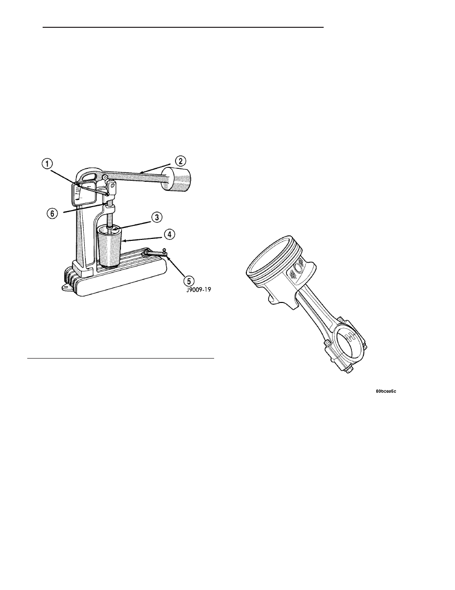
Fig. 55 Leak-Down Tester

1 - POINTER
2 - WEIGHTED ARM
3 - RAM
4 - CUP
5 - HANDLE
6 - PUSH ROD

Fig. 56 Piston and Connecting Rod Assembly

TJ

ENGINE 4.0L

9 - 111

HYDRAULIC LIFTERS (Continued)

MUST be replaced as complete sets. Tin coated
pistons should not be used as replacements for coated
pistons.

(4) The coating material is applied to the piston

after the final piston machining process. Measuring
the outside diameter of a coated piston will not pro-
vide accurate results (Fig. 57). Therefore measuring
the inside diameter of the cylinder bore with a dial
Bore Gauge is MANDATORY. To correctly select the
proper size piston, a cylinder bore gauge capable of
reading in 0.003 mm (.0001 in.) increments is
required.

(5) Piston

installation

into

the

cylinder

bore

requires slightly more pressure than that required
for non-coated pistons. The bonded coating on the
piston will give the appearance of a line-to-line fit
with the cylinder bore.

PISTON SIZE CHART

CYLINDER BORE SIZE

PISTON LETTER SIZE

98.438 - 98.448 mm

(3.8755 - 3.8759 in.)

A

98.448 - 98.458 mm

(3.8759 - 3.8763 in.)

B

98.458 - 98.468 mm

(3.8763 - 3.8767 in.)

C

98.468 - 98.478 mm

(3.8767 - 3.8771 in.)

D

98.478 - 98.488 mm

(3.8771 - 3.8775 in.)

E

98.488 - 98.498 mm

(3.8775 - 3.8779 in.)

F

REMOVAL

(1) Remove the engine cylinder head cover. (Refer

to

9

-

ENGINE/CYLINDER

HEAD/CYLINDER

HEAD COVER(S) - REMOVAL).

(2) Remove the rocker arms, bridges and pivots.
(3) Remove the push rods.
(4) Remove the engine cylinder head. (Refer to 9 -

ENGINE/CYLINDER HEAD - REMOVAL).

(5) Position the pistons one at a time near the bot-

tom of the stroke. Use a ridge reamer to remove the
ridge from the top end of the cylinder walls. Use a
protective cloth to collect the cuttings.

(6) Raise the vehicle.
(7) Drain the engine oil.

Fig. 57 Moly Coated Piston

1 - MOLY COATED
2 - MOLY COATED

Fig. 58 Bore Gauge

1 - FRONT
2 - BORE GAUGE
3 - CYLINDER BORE
4 - 49.5 MM (1-15/16 in.)

9 - 112

ENGINE 4.0L

TJ

PISTON & CONNECTING ROD (Continued)

(8) Remove the oil pan and gasket. (Refer to 9 -

ENGINE/LUBRICATION/OIL PAN - REMOVAL).

(9) Remove main bearing cap brace (Fig. 59).

(10) Remove the connecting rod bearing caps and

inserts. Mark the caps and rods with the cylinder
bore location. The connecting rods and caps are
stamped with a two letter combination (Fig. 60).

(11) Lower the vehicle until it is about 2 feet from

the floor.

CAUTION: Ensure that the connecting rod bolts DO
NOT scratch the crankshaft journals or cylinder
walls. Short pieces of rubber hose, slipped over the
rod bolts will provide protection during removal.

(12) Have an assistant push the piston and con-

necting rod assemblies up and through the top of the
cylinder bores (Fig. 61).

INSTALLATION

(1) Clean the cylinder bores thoroughly. Apply a

light film of clean engine oil to the bores with a clean
lint-free cloth.

(2) Install the piston rings on the pistons if

removed (Refer to 9 - ENGINE/ENGINE BLOCK/
PISTON RINGS - STANDARD PROCEDURE).

(3) Lubricate the piston and rings with clean

engine oil.

CAUTION: Ensure that connecting rod bolts DO
NOT scratch the crankshaft journals or cylinder
walls. Short pieces of rubber hose slipped over the
connecting rod bolts will provide protection during
installation.

Fig. 59 Main Bearings Caps and Brace

1 - BLOCK
2 - MAIN BEARING CAP BRACE

Fig. 60 Stamped Connecting Rods and Caps

1 - CONNECTING ROD CAP
2 - CONNECTING ROD

Fig. 61 Removal of Connecting Rod and Piston

Assembly

1 - PISTON
2 - CONNECTING ROD
3 - BLOCK

TJ

ENGINE 4.0L

9 - 113

PISTON & CONNECTING ROD (Continued)

(4) Use a piston ring compressor to install the con-

necting rod and piston assemblies through the top of
the cylinder bores (Fig. 62).

(5) Ensure the arrow on the piston top points to

the front of the engine (Fig. 62).

(6) Raise the vehicle.
(7) Each bearing insert is fitted to its respective

journal to obtain the specified clearance between the
bearing and the journal. In production, the select fit
is obtained by using various-sized, color-coded bear-
ing inserts as listed in the Connecting Rod Bearing
Fitting Chart. The color code appears on the edge of
the bearing insert. The size is not stamped on inserts
used for production of engines.

(8) The rod journal is identified during the engine

production by a color-coded paint mark on the adja-
cent cheek or counterweight toward the flange (rear)
end of the crankshaft. The color codes used to indi-
cate journal sizes are listed in the Connecting Rod
Bearing Fitting Chart.

(9) When

required,

upper

and

lower

bearing

inserts of different sizes may be used as a pair (refer
to Connecting Rod Bearing Fitting Chart). A stan-
dard size insert is sometimes used in combination
with a 0.025 mm (0.001 inch) undersize insert to
reduce clearance 0.013 mm (0.0005 inch).

CAUTION: DO NOT intermix bearing caps. Each
connecting rod and bearing cap are stamped with
the cylinder number. The stamp is located on a
machined surface adjacent to the oil squirt hole
that faces the camshaft side of the cylinder block.

(10) Install the connecting rod bearing caps and

inserts in the same positions as removed.

CAUTION: Verify that the oil squirt holes in the rods
face the camshaft and that the arrows on the pis-
tons face the front of the engine.

(11) Install main bearing cap brace (Fig. 59).

Tighten nuts to 47 N·m (35 ft. lbs.).

(12) Install the oil pan and gasket (Refer to 9 -

ENGINE/LUBRICATION/OIL

PAN

-

INSTALLA-

TION).

(13) Lower the vehicle.
(14) Install the engine cylinder head (Refer to 9 -

ENGINE/CYLINDER

HEAD

-

INSTALLATION),

push rods, rocker arms, bridges, pivots and engine
cylinder head cover (Refer to 9 - ENGINE/CYLIN-
DER

HEAD/CYLINDER

HEAD

COVER(S)

-

INSTALLATION).

(15) Fill the crankcase with engine oil.

PISTON RINGS

STANDARD PROCEDURE - PISTON RING
FITTING

(1) Carefully

clean

the

carbon

from

all

ring

grooves. Oil drain openings in the oil ring groove and
pin boss must be clear. DO NOT remove metal from
the grooves or lands. This will change ring-to-groove
clearances and will damage the ring-to-land seating.

(2) Be sure the piston ring grooves are free of

nicks and burrs.

(3) Measure the ring side clearance with a feeler

gauge fitted snugly between the ring land and ring
(Fig. 63) (Fig. 64). Rotate the ring in the groove. It
must move freely around circumference of the groove.

Fig. 62 Rod and Piston Assembly Installation

Fig. 63 Piston Dimensions

9 - 114

ENGINE 4.0L

TJ

PISTON & CONNECTING ROD (Continued)


Content   ..  447  448  449  450   ..