Jeep Wrangler TJ. Manual - part 448


  Index      Jeep     Jeep Wrangler TJ - service repair manual 2005 year


Search            


Content   ..  446  447  448  449   ..


Jeep Wrangler TJ. Manual - part 448


INSPECTION

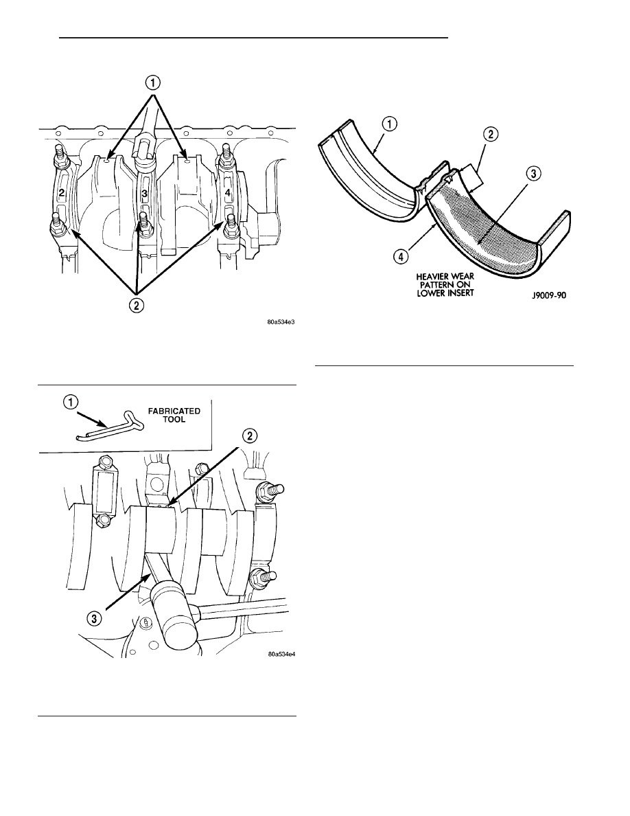
Wipe the inserts clean and inspect for abnormal

wear patterns and for metal or other foreign material

imbedded in the lining. Normal main bearing insert
wear patterns are illustrated (Fig. 48). In general the
lower bearing half will have a heaver wear pattern.

NOTE: If any of the crankshaft journals are scored,
remove the engine for crankshaft repair.

Inspect the back of the inserts for fractures, scrap-

ings or irregular wear patterns.

Inspect the upper insert locking tabs for damage.
Replace all damaged or worn bearing inserts.

INSTALLATION

(1) Lubricate the bearing surface of each insert

with engine oil.

(2) Loosen all the main bearing caps. Install the

main bearing upper inserts.

(3) Install the lower bearing inserts into the main

bearing caps.

(4) On the rear main cap, apply Mopar

t Gasket

Maker sealer on both sides of cylinder block as
shown in (Fig. 49). The dab of sealer should be 3 mm
(0.125 in.) in diameter.

(5) Apply Mopar

t Gasket Maker on the rear bear-

ing cap. The bead should be 2.3 mm (0.09 in.) in
diameter. DO NOT apply sealer to the lip of the seal.

(6) Install the main bearing cap(s) and lower

insert(s).

(7) Tighten the bolts of caps 1, 2, 4, 5, 6, and 7 to

54 N·m (40 ft. lbs.) torque. Now tighten these bolts to
95 N·m (70 ft. lbs.) torque. Finally, tighten these
bolts to 108 N·m (80 ft. lbs.) torque.

(8) Push the crankshaft forward and backward.

Load the crankshaft front or rear and tighten cap
bolt No.3 to 54 N·m (40 ft. lbs.) torque. Then tighten

Fig. 46 Removing Main Bearing Caps and Lower

Inserts

1 - CONNECTING ROD JOURNAL
2 - MAIN BEARING CAPS

Fig. 47 Removing Upper Inserts

1 - COTTER PIN
2 - BEARING INSERT
3 - TONGUE DEPRESSOR

Fig. 48 Main Bearing Wear Patterns

1 - UPPER INSERT
2 - NO WEAR IN THIS AREA
3 - LOW AREA IN BEARING LINING
4 - LOWER INSERT

TJ

ENGINE 4.0L

9 - 107

CRANKSHAFT MAIN BEARINGS (Continued)

to 95 N·m (70 ft. lbs.) torque and finally tighten to
108 N·m (80 ft. lbs.) torque.

(9) Rotate the crankshaft after tightening each

main bearing cap to ensure the crankshaft rotates
freely.

(10) Check crankshaft end play. Crankshaft end

play is controlled by the thrust bearing which is
flange and installed at the No.2 main bearing posi-
tion.

(a) Attach a magnetic base dial indicator to the

cylinder block at either the front or rear of the
engine.

(b) Position the dial indicator rod so that it is

parallel to the center line of the crankshaft.

(c) Pry the crankshaft forward, position the dial

indicator to zero.

(d) Pry the crankshaft forward and backward.

Note the dial indicator readings. End play is the
difference between the high and low measurements
(Fig. 50). Correct end play is 0.038-0.165 mm
(0.0015-0.0065 inch). The desired specifications are
0.051-0.064 mm (0.002-0.0025 inch).

(e) If end play is not within specification, inspect

crankshaft thrust faces for wear. If no wear is
apparent, replace the thrust bearing and measure
end play. If end play is still not within specifica-
tion, replace the crankshaft.

(11) If the crankshaft was removed, install the

crankshaft into the cylinder block.

(12) Install main bearing cap brace tighten nuts to

47 N·m (35 ft. lbs.) torque.

(13) Install oil pump assy. and tighten attaching

bolts to 23 N·m (17 ft. lbs.)

(14) Install the oil pan (Refer to 9 - ENGINE/LU-

BRICATION/OIL PAN - INSTALLATION).

(15) Install the drain plug. Tighten the plug to 34

N·m (25 ft. lbs.) torque.

(16) Lower the vehicle.
(17) Install the spark plugs. Tighten the plugs to

37 N·m (27 ft. lbs.) torque.

(18) Fill the oil pan with engine oil to the full

mark on the dipstick level.

(19) Connect negative cable to battery.

CRANKSHAFT OIL SEAL -
FRONT

REMOVAL

This procedure is done with the timing case cover

installed.

(1) Disconnect negative cable from battery.
(2) Remove the serpentine drive belt (Refer to 7 -

COOLING/ACCESSORY

DRIVE/DRIVE

BELTS

-

REMOVAL).

(3) Remove the vibration damper (Refer to 9 -

ENGINE/ENGINE BLOCK/VIBRATION DAMPER -
REMOVAL).

(4) Remove the radiator shroud.
(5) Carefully remove the oil seal. Make sure seal

bore is clean.

Fig. 49 Location of Sealer

1 - DOWEL
2 - SEALER LOCATIONS
3 - CYLINDER BLOCK
4 - HALFWAY BETWEEN
5 - REAR FACE OF CYLINDER BLOCK
6 - 3mm (0.125 in.)

Fig. 50 Crankshaft End Play Measurement

1 - DIAL INDICATOR
2 - CRANKSHAFT

9 - 108

ENGINE 4.0L

TJ

CRANKSHAFT MAIN BEARINGS (Continued)

INSTALLATION

This procedure is done with the timing case cover

installed.

(1) Position the replacement oil seal on Timing Case

Cover Alignment and Seal Installation Tool 6139 with
seal open end facing inward. Apply a light film of Per-
fect Seal, or equivalent, on the outside diameter of the
seal. Lightly coat the crankshaft with engine oil.

(2) Position the tool and seal over the end of the

crankshaft and insert a draw screw tool into Seal
Installation Tool 6139 (Fig. 51). Tighten the nut
against the tool until it contacts the cover.

(3) Remove the tools. Apply a light film of engine oil

on the vibration damper hub contact surface of the seal.

(4) Apply Mopar

t Silicone Rubber Adhesive Seal-

ant to the keyway in the crankshaft and insert the
key. With the key inserted in the keyway in the
crankshaft, install the vibration damper (Refer to 9 -
ENGINE/ENGINE BLOCK/VIBRATION DAMPER -
INSTALLATION).

(5) Install the serpentine belt (Refer to 7 - COOL-

ING/ACCESSORY DRIVE/DRIVE BELTS - INSTAL-
LATION).

(6) Install the radiator shroud.
(7) Connect negative cable to battery.

CRANKSHAFT OIL SEAL -
REAR

REMOVAL

The crankshaft rear main bearing oil seal consists of

two half pieces of viton with a single lip that effectively
seals the rear of the crankshaft. Replace the upper and
lower seal halves as a unit to ensure leak-free operation.

(1) Remove transmission inspection cover.
(2) Remove oil pan. (Refer to 9 - ENGINE/LUBRI-

CATION/OIL PAN - REMOVAL)

(3) Remove main bearing cap brace.
(4) Remove rear main bearing cap (No.7).
(5) Push upper seal out of the groove. Ensure that

the crankshaft and seal groove are not damaged.

(6) Remove lower half of the seal from the bearing

cap.

INSTALLATION

The crankshaft rear main bearing oil seal consists

of two half pieces of viton with a single lip that effec-
tively seals the rear of the crankshaft. Replace the
upper and lower seal halves as a unit to ensure leak-
free operation.

(1) Wipe the seal surface area of the crankshaft

until it is clean.

(2) Apply a thin coat of engine oil.
(3) Coat lip of the seal with engine oil.
(4) Carefully position the upper seal into the

groove in the cylinder block. The lip of the seal faces
toward the front of the engine.

(5) Apply Mopar

t Gasket Maker sealer on both

sides of cylinder block as shown in (Fig. 52). The dab
of sealer should be 3 mm (0.125 in.) in diameter.

Fig. 52 Location of Sealer

1 - DOWEL
2 - SEALER LOCATIONS
3 - CYLINDER BLOCK
4 - HALFWAY BETWEEN
5 - REAR FACE OF CYLINDER BLOCK
6 - 3mm (0.125 in.)

Fig. 51 Timing Case Cover Oil Seal Installation

1 - SEAL INSTALLATION TOOL
2 - DRAW SCREW TOOL

TJ

ENGINE 4.0L

9 - 109

CRANKSHAFT OIL SEAL - FRONT (Continued)

(6) Apply Mopar

t Gasket Maker on the rear bear-

ing cap (Fig. 52). The bead should be 2.3 mm (0.09
in.) in diameter. DO NOT apply sealer to the lip of
the seal.

(7) Position the lower seal into the bearing cap

recess and seat it firmly. Be sure the seal is flush
with the cylinder block pan rail.

(8) Coat the outer curved surface of the lower seal

with soap and the lip of the seal with engine oil.

(9) Install the rear main bearing cap. DO NOT

strike the cap more than twice for proper engage-
ment.

(10) Tighten all main bearing bolts to 108 N·m (80

ft. lbs.) torque.

(11) Install the main bearing cap brace. Tighten

nuts to 47 N·m (35 ft. lbs.).

(12) Install the oil pan gasket and oil pan (Refer to

9 - ENGINE/LUBRICATION/OIL PAN - INSTALLA-
TION).

(13) Apply Mopar

t Silicone Rubber Adhesive Seal-

ant on cylinder block to rear main bearing cap cor-
ners and cylinder block to front cover joints (four
places) (Fig. 53)

(14) Install transmission inspection cover.

HYDRAULIC LIFTERS

DESCRIPTION

Valve lash is controlled by hydraulic tappets

located inside the cylinder block, in tappet bores
above the camshaft.

REMOVAL

NOTE: Retain all the components in the same order
as removed.

(1) Remove the engine cylinder head (Refer to 9 -

ENGINE/CYLINDER HEAD - REMOVAL).

(2) Remove the push rods.
(3) Remove the tappets through the push rod open-

ings in the cylinder block with a Hydraulic Valve
Tappet Removal/Installation Tool (Fig. 54).

CLEANING

Clean each tappet assembly in cleaning solvent to

remove all varnish, gum and sludge deposits.

INSPECTION

Inspect for indications of scuffing on the side and

base of each tappet body.

Inspect each tappet base for concave wear with a

straightedge positioned across the base. If the base is
concave, the corresponding lobe on the camshaft is
also worn. Replace the camshaft and tappets.

After cleaning and inspection, test each tappet for

specified leak-down rate tolerance to ensure zero-lash
operation (Fig. 55).

Swing the weighted arm of the hydraulic valve tap-

pet tester away from the ram of the Leak-Down
Tester.

(1) Place a 7.925-7.950 mm (0.312-0.313 inch)

diameter ball bearing on the plunger cap of the tap-
pet.

(2) Lift the ram and position the tappet (with the

ball bearing) inside the tester cup.

(3) Lower the ram, then adjust the nose of the ram

until it contacts the ball bearing. DO NOT tighten
the hex nut on the ram.

(4) Fill the tester cup with hydraulic valve tappet

test oil until the tappet is completely submerged.

(5) Swing the weighted arm onto the push rod and

pump the tappet plunger up and down to remove air.
When the air bubbles cease, swing the weighted arm
away and allow the plunger to rise to the normal
position.

(6) Adjust the nose of the ram to align the pointer

with the SET mark on the scale of the tester and
tighten the hex nut.

Fig. 53 Oil Pan

1 - SEALER LOCATIONS

Fig. 54 HYDRAULIC VALVE TAPPET REMOVAL -

4.0L

1 - HYDRAULIC TAPPET REMOVAL TOOL
2 - CYLINDER BLOCK

9 - 110

ENGINE 4.0L

TJ

CRANKSHAFT OIL SEAL - REAR (Continued)


Content   ..  446  447  448  449   ..