Jeep Wrangler TJ. Manual - part 447
(11) FOR EXAMPLE: If the initial clearance was
0.0762 mm (0.003 inch), 0.025 mm (0.001 inch)
undersize inserts would reduce the clearance by
0.025 mm (0.001 inch). The clearance would be 0.002
inch and within specification. A 0.051 mm (0.002
inch) undersize insert would reduce the initial clear-
ance an additional 0.013 mm (0.0005 inch). The
clearance would then be 0.038 mm (0.0015 inch).
(12) Repeat the Plastigage measurement to verify
your bearing selection prior to final assembly.
(13) Once you have selected the proper insert,
install the insert and cap. Tighten the connecting rod
bolts to 45 N·m (33 ft. lbs.) torque.
SIDE CLEARANCE MEASUREMENT
Slide snug-fitting feeler gauge between the con-
necting rod and crankshaft journal flange (Fig. 41).
(Refer to 9 - ENGINE - SPECIFICATIONS). Replace
the connecting rod if the side clearance is not within
specification.
CRANKSHAFT
DESCRIPTION
The crankshaft is constructed of nodular cast iron.
The crankshaft is a crosshaped four throw design
with eight counterweights for balancing purposes.
The crankshaft is supported by seven select main
bearings with the number three serving as the thrust
washer location. The main journals of the crankshaft
are cross drilled to improve rod bearing lubrication.
The select fit main bearing markings are located on
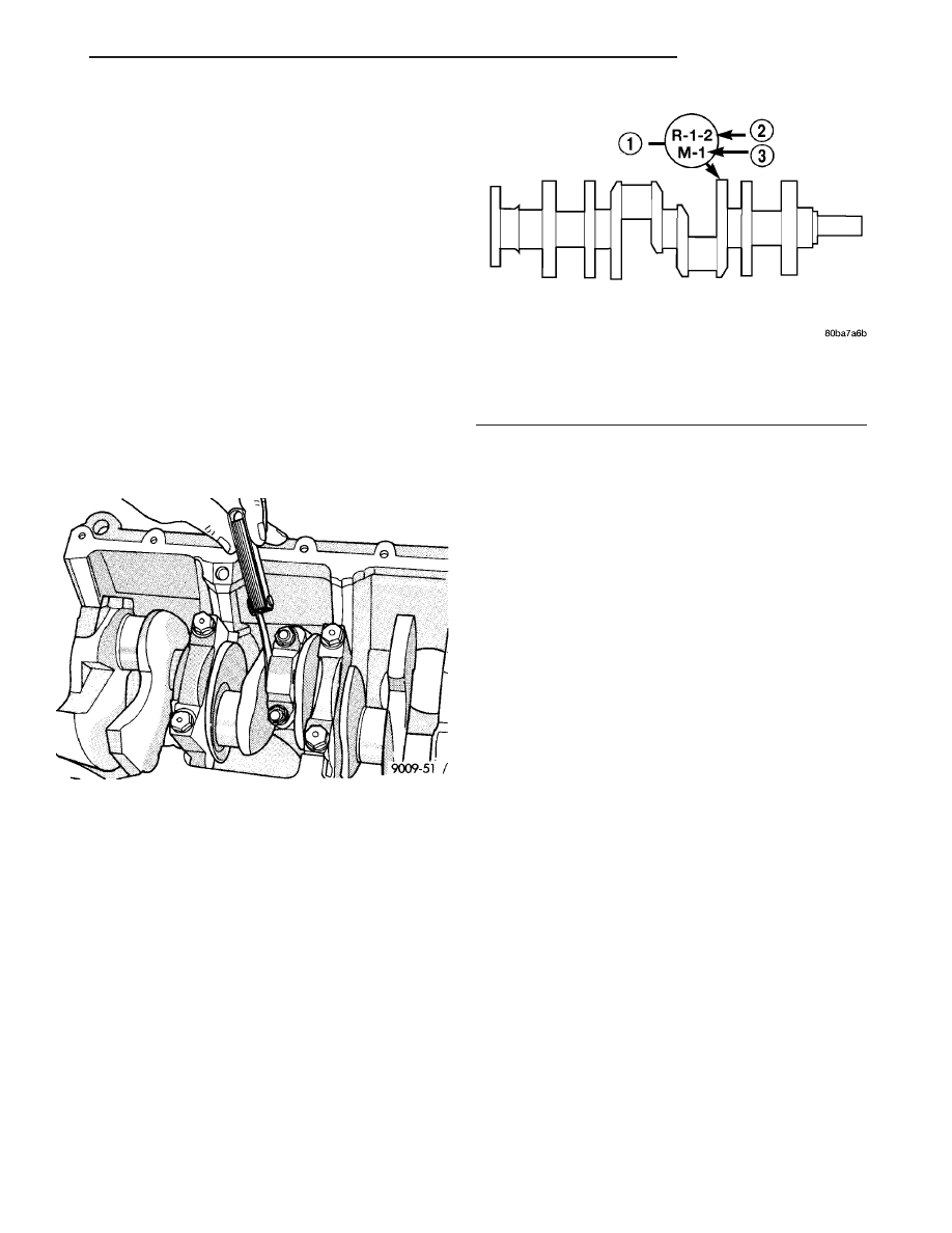
the crankshaft counter weights. The crankshaft rear
oil seal is a two piece design. The front oil seal is a
one piece design retained in the timing chain cover
(Fig. 42).
CRANKSHAFT MAIN
BEARINGS
STANDARD PROCEDURE - FITTING
CRANKSHAFT MAIN BEARINGS
FITTING BEARINGS (CRANKSHAFT INSTALLED)
The main bearing caps, numbered (front to rear)
from 1 through 7 have an arrow to indicate the for-
ward position. The upper main bearing inserts are
grooved to provide oil channels while the lower
inserts are smooth.
Each bearing insert pair is selectively fitted to its
respective journal to obtain the specified operating
clearance. In production, the select fit is obtained by
using various-sized color-coded bearing insert pairs
as listed in the Main Bearing Fitting Chart. The
bearing color code appears on the edge of the insert.
The size is not stamped on bearing inserts used
for engine production.
The main bearing journal size (diameter) is identi-
fied by a color-coded paint mark (Fig. 43)on the adja-
cent cheek or counterweight towards the rear of the
crankshaft (flange end). The rear main journal, is
identified by a color-coded paint mark on the crank-
shaft rear flange.
When required, upper and lower bearing inserts of
different sizes may be used as a pair. A standard size
insert is sometimes used in combination with a 0.025
mm (0.001 inch) undersize insert to reduce the clear-
ance by 0.013 mm (0.0005 inch). Never use a pair
of bearing inserts with greater than a 0.025 mm
(0.001 inch) difference in size. Refer to the
Bearing Insert Pair Chart.
NOTE: When replacing inserts, the odd size inserts
must be either all on the top (in cylinder block) or
all on the bottom (in main bearing cap).
Fig. 41 Checking Connecting Rod Side Clearance -
Typical
Fig. 42 Crankshaft with Select Fit Marking Location
1 - 1/4” LETTERS
2 - (ROD)
3 - (MAIN)
TJ
ENGINE 4.0L
9 - 103
CONNECTING ROD BEARINGS (Continued)