Jeep Wrangler TJ. Manual - part 445


  Index      Jeep     Jeep Wrangler TJ - service repair manual 2005 year


Search            


Content   ..  443  444  445  446   ..


Jeep Wrangler TJ. Manual - part 445


INSTALLATION

NOTE: This procedure can be done with the engine
in or out of the vehicle.

(1) Lubricate the ball ends of the push rods with

Mopar

t Engine Oil Supplement, or equivalent and

install push rods in their original locations. Ensure
that the bottom end of each push rod is centered in
the tappet plunger cap seat.

(2) Using Mopar

t Engine Oil Supplement, or

equivalent, lubricate the area of the rocker arm that
the pivot contacts. Install rocker arms, pivots and
bridge above each cylinder in their originally position
(Fig. 24).

(3) Loosely install the capscrews through each

bridge.

(4) At each bridge, tighten the capscrews alter-

nately, one turn at a time, to avoid damaging the
bridge. Tighten the capscrews to 28 N·m (21 ft. lbs.)
torque.

(5) Install the engine cylinder head cover (Refer to

9 - ENGINE/CYLINDER HEAD/CYLINDER HEAD
COVER(S) - INSTALLATION).

VALVE STEM SEALS

DESCRIPTION

The valve stem seals (Fig. 25) are made of rubber

and incorporate a garter spring to maintain consis-
tent lubrication control.
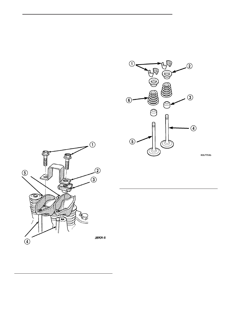
Fig. 24 Rocker Arm

1 - CAPSCREWS
2 - BRIDGE
3 - PIVOT ASSEMBLY
4 - PUSH RODS
5 - ROCKER ARMS

Fig. 25 Valve

1 - VALVE LOCKS (3–BEAD)
2 - RETAINER
3 - VALVE STEM OIL SEAL
4 - INTAKE VALVE
5 - EXHAUST VALVE
6 - VALVE SPRING

TJ

ENGINE 4.0L

9 - 95

ROCKER ARM / ADJUSTER ASSEMBLY (Continued)

VALVE SPRINGS

DESCRIPTION

The valve springs (Fig. 26) are made of high

strength silicon chrome spring steel. The springs are
common for both intake and exhaust valves.

STANDARD PROCEDURE - VALVE SPRING
TENSION TEST

Clean all carbon deposits from the combustion

chambers, valve ports, valve stems, valve stem
guides and head.

Use a universal Valve Spring Tester and a torque

wrench to test each valve spring for the specified ten-
sion value (Fig. 27).

Replace valve springs that are not within specifica-

tions.

REMOVAL

NOTE: This procedure can be done with the engine
cylinder head installed on the block.

Inspect the valve stems, especially the grooves. An

Arkansas smooth stone should be used to remove
nicks and high spots.

Each valve spring is held in place by a retainer

and a set of conical valve locks. The locks can be
removed only by compressing the valve spring.

(1) Remove the engine cylinder head cover (Refer

to

9

-

ENGINE/CYLINDER

HEAD/CYLINDER

HEAD COVER(S) - REMOVAL).

(2) Remove cap screws, bridge and pivot assem-

blies and rocker arms (Refer to 9 - ENGINE/CYLIN-
DER HEAD/ROCKER ARM / ADJUSTER ASSY -
REMOVAL) for access to each valve spring to be
removed.

(3) Remove push rods. Retain the push rods,

bridges, pivots and rocker arms in the same
order and position as removed.

(4) Inspect the springs and retainer for cracks and

possible signs of weakening.

(5) Remove the spark plug(s) adjacent to the cylin-

der(s) below the valve springs to be removed.

(6) Connect an air hose to the adapter and apply

air pressure slowly. Maintain at least 621 kPa (90
psi) of air pressure in the cylinder to hold the valves
against their seats. For vehicles equipped with an air
conditioner, use a flexible air adaptor when servicing
the No.1 cylinder.

(7) Tap the retainer or tip with a rawhide hammer

to loosen the lock from the retainer. Use Valve Spring
Compressor Tool MD-998772A to compress the spring
and remove the locks (Fig. 28).

(8) Remove valve spring and retainer (Fig. 28).
(9) Remove valve stem oil seals (Fig. 28). Note the

valve seals are different for intake and exhaust
valves. The top of each seal is marked either INT
(intake/black in color) or EXH (exhaust/brown in
color). DO NOT mix the seals.

Fig. 26 VALVE AND KEEPER CONFIGURATION 4.0L

1 - VALVE LOCKS (3–BEAD)
2 - RETAINER
3 - VALVE STEM OIL SEAL
4 - INTAKE VALVE
5 - EXHAUST VALVE
6 - VALVE SPRING

Fig. 27 Valve Spring Tester

1 - TORQUE WRENCH
2 - VALVE SPRING TESTER

9 - 96

ENGINE 4.0L

TJ

INSTALLATION

NOTE: This procedure can be done with the engine
cylinder head installed on the block.

CAUTION: Install oil seals carefully to prevent dam-
age from the sharp edges of the valve spring lock
grove.

(1) Lightly push the valve seal over the valve stem

and valve guide boss. Be sure the seal is completely
seated on the valve guide boss.

(2) Install valve spring and retainer (Fig. 29).
(3) Compress the valve spring with Valve Spring

Compressor Tool MD-998772A and insert the valve
locks. Release the spring tension and remove the
tool. Tap the spring from side-to-side to ensure that
the spring is seated properly on the engine cylinder
head.

(4) Release air pressure and disconnect the air

hose. Remove the adaptor from the spark plug hole
and install the spark plug.

(5) Repeat the procedures for each remaining valve

spring to be removed.

(6) Install the push rods. Ensure the bottom end of

each rod is centered in the plunger cap seat of the
hydraulic valve tappet.

(7) Install the rocker arms, pivots and bridge

(Refer to 9 - ENGINE/CYLINDER HEAD/ROCKER
ARM / ADJUSTER ASSY - INSTALLATION) at their
original location.

(8) Install the engine cylinder head cover (Refer to

9 - ENGINE/CYLINDER HEAD/CYLINDER HEAD
COVER(S) - INSTALLATION).

ENGINE BLOCK

CLEANING

Thoroughly clean the oil pan and engine block gas-

ket surfaces.

Use compressed air to clean out:
• The galley at the oil filter adaptor hole.

• The front and rear oil galley holes.

• The feed holes for the crankshaft main bearings.
Once the block has been completely cleaned, apply

Loctite PST pipe sealant with Teflon 592 to the
threads of the front and rear oil galley plugs. Tighten
the plugs to 34 N·m (25 ft. lbs.) torque.

Fig. 28 Valve and Valve Components

1 - VALVE LOCKS (3–BEAD)
2 - RETAINER
3 - VALVE STEM OIL SEAL
4 - INTAKE VALVE
5 - EXHAUST VALVE
6 - VALVE SPRING

Fig. 29 Valve and Valve

1 - VALVE LOCKS (3–BEAD)
2 - RETAINER
3 - VALVE STEM OIL SEAL
4 - INTAKE VALVE
5 - EXHAUST VALVE
6 - VALVE SPRING

TJ

ENGINE 4.0L

9 - 97

VALVE SPRINGS (Continued)

INSPECTION

(1) It is mandatory to use a dial bore gauge to

measure each cylinder bore diameter (Fig. 30). To
correctly select the proper size piston, a cylinder bore
gauge, capable of reading in 0.003 mm (.0001 in.)
INCREMENTS is required. If a bore gauge is not
available, do not use an inside micrometer.

(2) Measure the inside diameter of the cylinder

bore at three levels below top of bore. Start perpen-
dicular (across or at 90 degrees) to the axis of the
crankshaft and then take two additional reading.

(3) Measure the cylinder bore diameter crosswise

to the cylinder block near the top of the bore. Repeat
the measurement near the middle of the bore, then
repeat the measurement near the bottom of the bore.

(4) Determine taper by subtracting the smaller

diameter from the larger diameter.

(5) Rotate measuring device 90° and repeat steps

above.

(6) Determine out-of-roundness by comparing the

difference between each measurement.

(7) If cylinder bore taper does not exceed 0.025

mm (0.001 inch) and out-of-roundness does not
exceed 0.025 mm (0.001 inch), the cylinder bore can
be honed. If the cylinder bore taper or out- of-round
condition exceeds these maximum limits, the cylinder
must be bored and then honed to accept an oversize
piston. A slight amount of taper always exists in the
cylinder bore after the engine has been in use for a
period of time.

CAMSHAFT & BEARINGS (IN
BLOCK)

DESCRIPTION

The camshaft is made of gray cast iron with twelve

machined lobes and four bearing journals (Fig. 31).
When the camshaft rotates the lobes actuate the tap-
pets and push rods, forcing upward on the rocker
arms which applies downward force on the valves.

REMOVAL

REMOVAL - CAMSHAFT BEARINGS

The camshaft rotates within four steel-shelled,

babbitt-lined bearings that are pressed into the cyl-
inder block and then line reamed. The camshaft
bearing bores and bearing diameters are not the
same size. They are stepped down in 0.254 mm
(0.010 inch) increments from the front bearing (larg-
est) to the rear bearing (smallest). This permits eas-
ier removal and installation of the camshaft. The
camshaft bearings are pressure lubricated. Camshaft
end play is maintained by the thrust plate.

(1) Remove the camshaft (Refer to 9 - ENGINE/

ENGINE BLOCK/CAMSHAFT & BEARINGS (IN
BLOCK) - REMOVAL).

Fig. 30 Cylinder Bore Measurement

Fig. 31 Camshaft—Typical

1 - CAMSHAFT
2 - LOBES
3 - BEARING JOURNAL

9 - 98

ENGINE 4.0L

TJ

ENGINE BLOCK (Continued)


Content   ..  443  444  445  446   ..