Jeep Wrangler TJ. Manual - part 436


  Index      Jeep     Jeep Wrangler TJ - service repair manual 2005 year


Search            


Content   ..  434  435  436  437   ..


Jeep Wrangler TJ. Manual - part 436


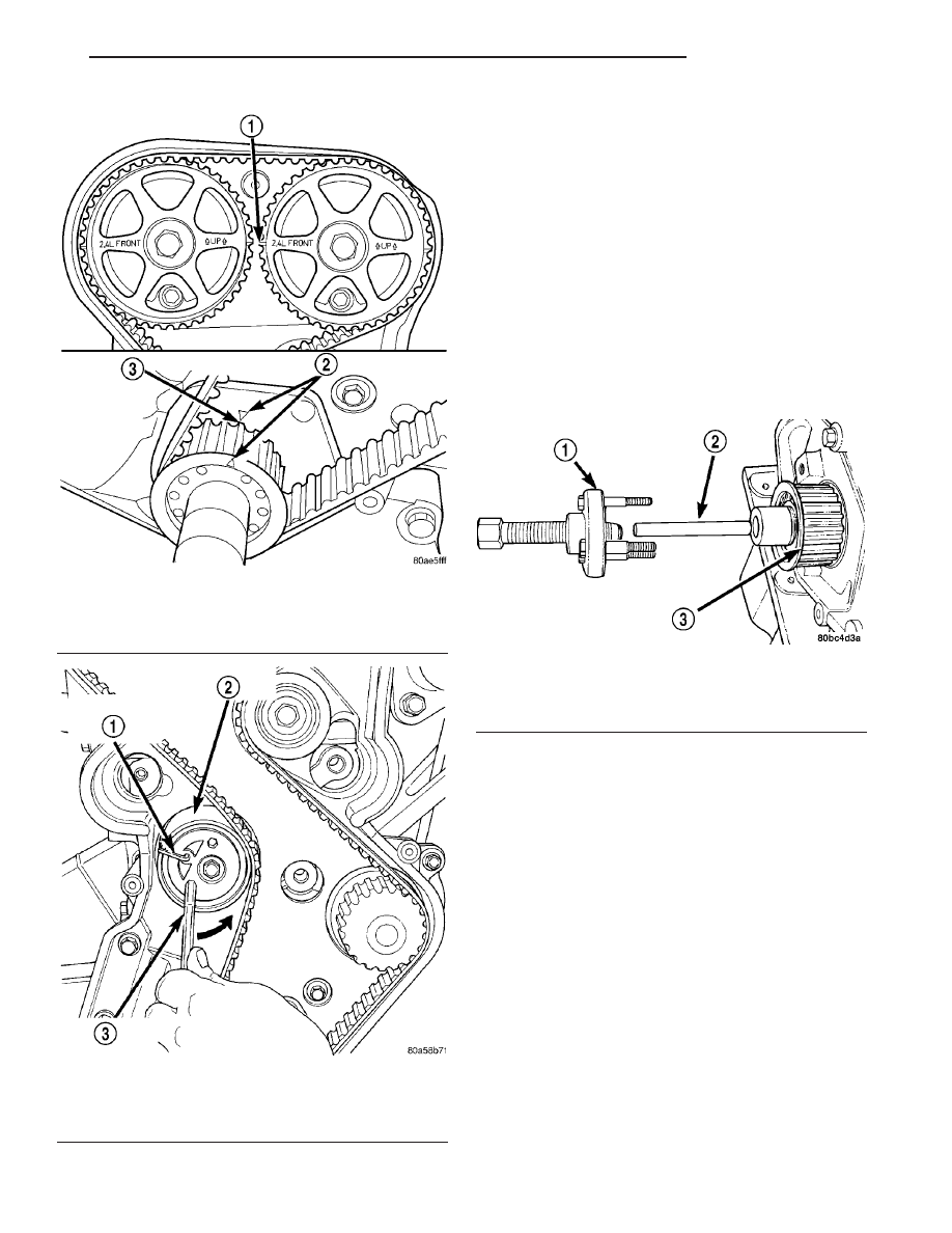
(10) Install 6 mm Allen wrench into belt tensioner.

Before rotating the tensioner, insert the long end of a
1/8” or 3 mm Allen wrench into the pin hole on the
front of the tensioner (Fig. 98). While rotating the
tensioner counterclockwise, push in lightly on the
1/8” or 3 mm Allen wrench, until it slides into the
locking hole.

(11) Remove timing belt.

CRANKSHAFT SPROCKET

(1) Disconnect negative battery cable.
(2) Remove timing belt (Refer to 9 - ENGINE/

VALVE

TIMING/TIMING

BELT/CHAIN

AND

SPROCKETS - REMOVAL).

(3) Remove

crankshaft

sprocket

using

Special

Tools 6793 and insert C-4685-C2 (Fig. 99).

CLEANING

Do Not attempt to clean a timing belt. If contami-

nation from oil, grease, or coolants have occurred, the
timing belt should be replaced.

Clean all sprockets using a suitable solvent. Clean

all sprocket grooves of any debris.

INSTALLATION

CRANKSHAFT SPROCKET

CAUTION: The crankshaft sprocket is set to a pre-
determined depth from the factory for correct tim-
ing belt tracking. If removed, use of Special Tool
6792 is required to set the sprocket to original
installation depth. An incorrectly installed sprocket
will result in timing belt and engine damage.

Fig. 97 Crankshaft and Camshaft Timing

1 - CAMSHAFT TIMING MARKS
2 - CRANKSHAFT TDC MARKS
3 - TRAILING EDGE OF SPROCKET TOOTH

Fig. 98 Locking Timing Tensioner

1 - 1/8 OR 3mm ALLEN WRENCH
2 - BELT TENSIONER
3 - 6mm ALLEN WRENCH

Fig. 99 Crankshaft Sprocket - Removal

1 - SPECIAL TOOL 6793
2 - SPECIAL TOOL C-4685–C2
3 - CRANKSHAFT SPROCKET

TJ

ENGINE 2.4L

9 - 59

TIMING BELT AND SPROCKET(S) (Continued)

(1) Install crankshaft sprocket using Special Tool

6792 (Fig. 100).

(2) Install timing belt. (Refer to 9 - ENGINE/

VALVE

TIMING/TIMING

BELT/CHAIN

AND

SPROCKETS - INSTALLATION)

TIMING BELT

CAUTION: The crankshaft sprocket is set to a pre-
determined depth from the factory for correct tim-
ing belt tracking. If removed, use of Special Tool
6792 is required to set the sprocket to original
installation depth. An incorrectly installed sprocket
will result in timing belt and engine damage.

(1) Set crankshaft sprocket to TDC by aligning the

sprocket with the arrow on the oil pump housing.

(2) Set

camshafts

timing

marks

so

that

the

exhaust camshaft sprocket is a 1/2 notch below the
intake camshaft sprocket (Fig. 101).

CAUTION: Ensure that the arrows on both camshaft
sprockets are facing up.

(3) Install timing belt. Starting at the crankshaft,

go around the water pump sprocket, idler pulley,
camshaft sprockets and then around the tensioner
(Fig. 102).

(4) Move the exhaust camshaft sprocket counterclock-

wise (Fig. 102) to align marks and take up belt slack.

(5) Insert a 6 mm Allen wrench into the hexagon

opening located on the top plate of the belt tensioner
pulley. Rotate the top plate COUNTERCLOCK-
WISE
. The tensioner pulley will move against the
belt and the tensioner setting notch will eventually
start to move clockwise. Watching the movement of
the setting notch, continue rotating the top plate

Fig. 100 Crankshaft Sprocket - Installation

1 - SPECIAL TOOL 6792
2 - TIGHTEN NUT TO INSTALL

Fig. 101 Camshaft Sprocket Alignment

1 - CAMSHAFT SPROCKET-EXHAUST
2 - CAMSHAFT SPROCKET-INTAKE
3 - 1/2 NOTCH LOCATION

Fig. 102 Timing Belt - Installation - Typical

1 - ROTATE CAMSHAFT SPROCKET TO TAKE UP BELT SLACK
2 - CAMSHAFT TIMING MARKS 1/2 NOTCH LOCATION
3 - CRANKSHAFT AT TDC
4 - INSTALL BELT IN THIS DIRECTION

9 - 60

ENGINE 2.4L

TJ

TIMING BELT AND SPROCKET(S) (Continued)

counterclockwise until the setting notch is aligned
with the spring tang (Fig. 103). Using the allen
wrench to prevent the top plate from moving, torque
the tensioner lock nut to 30 N·m (22 ft. lbs.). Setting
notch and spring tang should remain aligned after
lock nut is torqued.

(6) Remove allen wrench and torque wrench.

NOTE: Repositioning the crankshaft to the TDC
position must be done only during the CLOCKWISE
rotation movement. If TDC is missed, rotate a fur-
ther two revolutions until TDC is achieved. DO NOT
rotate crankshaft counterclockwise as this will
make verification of proper tensioner setting impos-
sible.

(7) Once the timing belt has been installed and

tensioner adjusted, rotate the crankshaft CLOCK-
WISE two complete revolutions manually for seating
of the belt, until the crankshaft is repositioned at the
TDC position. Verify that the camshaft and crank-
shaft timing marks are in proper position (Fig. 104).

(8) Check if the spring tang is within the tolerance

window (Fig. 105). If the spring tang is within the
tolerance window, the installation process is complete
and nothing further is required. If the spring tang is
not within the tolerance window, repeat Steps 5
through 7.

Fig. 103 Timing Belt Tension Adjustment

1 - ALIGN SETTING NOTCH WITH SPRING TANG
2 - TOP PLATE
3 - 6mm ALLEN WRENCH
4 - LOCK NUT
5 - SETTING NOTCH
6 - SPRING TANG

Fig. 104 Crankshaft and Camshaft Timing

1 - CAMSHAFT TIMING MARKS
2 - CRANKSHAFT TDC MARKS
3 - TRAILING EDGE OF SPROCKET TOOTH

Fig. 105 Timing Belt Tension Verification

1 - SPRING TANG
2 - TOLERANCE WINDOW

TJ

ENGINE 2.4L

9 - 61

TIMING BELT AND SPROCKET(S) (Continued)

(9) Install timing belt front covers and bolts.

(Refer to 9 - ENGINE/VALVE TIMING/TIMING
BELT / CHAIN COVER(S) - INSTALLATION)

(10) Install air conditioning/generator belt ten-

sioner and pulley. (Refer to 7 - COOLING/ACCES-
SORY

DRIVE/BELT

TENSIONERS

-

INSTALLATION)

(11) Install crankshaft vibration damper. (Refer to

9

-

ENGINE/ENGINE

BLOCK/VIBRATION

DAMPER - INSTALLATION)

(12) Install accessory drive belts. (Refer to 7 -

COOLING/ACCESSORY

DRIVE/DRIVE

BELTS

-

INSTALLATION)

(13) Install drive belt splash shield.
(14) Install air cleaner housing, upper cover, and

clean air tube.

TIMING BELT TENSIONER &
PULLEY

REMOVAL

(1) Remove the timing belt. (Refer to 9 - ENGINE/

VALVE

TIMING/TIMING

BELT/CHAIN

AND

SPROCKETS - REMOVAL)

(2) Remove timing belt idler pulley.
(3) Hold camshaft sprocket with Special Tool 6847

while removing bolt (Fig. 106). Remove both cam
sprockets.

(4) Remove rear timing belt cover fasteners and

remove cover from engine (Fig. 107).

(5) Remove lower bolt attaching timing belt ten-

sioner assembly to engine and remove tensioner as
an assembly
.

INSTALLATION

(1) Align timing belt tensioner assembly to engine

and install lower mounting bolt but do not tighten.
To properly align tensioner assembly—install one of
the engine bracket mounting bolts (M10) 5 to 7 turns
into the tensioner’s upper mounting location.

(2) Torque the tensioner’s lower mounting bolt to

61 N·m (45 ft. lbs.). Remove the upper bolt used for
tensioner alignment.

(3) Install rear timing belt cover and fasteners.
(4) Install timing belt idler pulley and torque

mounting bolt to 61 N·m (45 ft. lbs.).

(5) Install camshaft sprockets. Use Special Tool

6847 to hold sprockets, torque bolts to 101 N·m (75
ft. lbs.).

(6) Install the timing belt. (Refer to 9 - ENGINE/

VALVE

TIMING/TIMING

BELT/CHAIN

AND

SPROCKETS - INSTALLATION)

Fig. 106 Camshaft Sprocket - Removal/Installation

1 - SPECIAL TOOL 6847

Fig. 107 TIMING BELT REAR COVER FASTENERS

1 - OUTER COVER TO REAR COVER FASTENERS (3)
2 - REAR COVER TO CYLINDER HEAD FASTENERS
3 - OUTER COVER TO REAR COVER FASTENERS (3)
4 - INNER COVER TO BLOCK FASTENERS

9 - 62

ENGINE 2.4L

TJ

TIMING BELT AND SPROCKET(S) (Continued)


Content   ..  434  435  436  437   ..