Jeep Wrangler TJ. Manual - part 420


  Index      Jeep     Jeep Wrangler TJ - service repair manual 2005 year


Search            


Content   ..  418  419  420  421   ..


Jeep Wrangler TJ. Manual - part 420


(2) Gently and evenly press the PDC relay wedge

down into the relay cassette until both of the latches
are fully engaged.

(3) Install each of the removed relays into the

proper cavities of the PDC relay wedge.

(4) Install the PDC housing lower cover.

PDC RELAY CASSETTE INSTALLATION

(1) Move the faulty PDC relay cassette with its

wiring away from the bottom of the PDC housing far
enough to allow the replacement relay cassette to be
installed into the PDC.

(2) Using the faulty relay cassette as a guide, be

certain that the replacement relay cassette is cor-
rectly oriented before installing it into the PDC hous-
ing.

(3) From the bottom of the PDC housing, align and

insert the replacement relay cassette into the PDC.
Press the relay cassette up into the PDC until both
of the latches are fully engaged.

CAUTION: Proper care must be taken to be certain
that the wiring and terminals from the faulty PDC
relay cassette are installed in the correct terminal
cavities of the replacement relay cassette. To pre-
vent mistakes it is recommended that the wiring
and terminals be removed from the faulty relay cas-
sette one cavity at a time, repaired or spliced as
necessary, then installed securely into the correct
cavity of the replacement relay cassette. If you are
not absolutely certain into which cavity a terminal
should be installed, refer to Power Distribution in
the index of this service manual for the location of
complete PDC wiring diagrams.

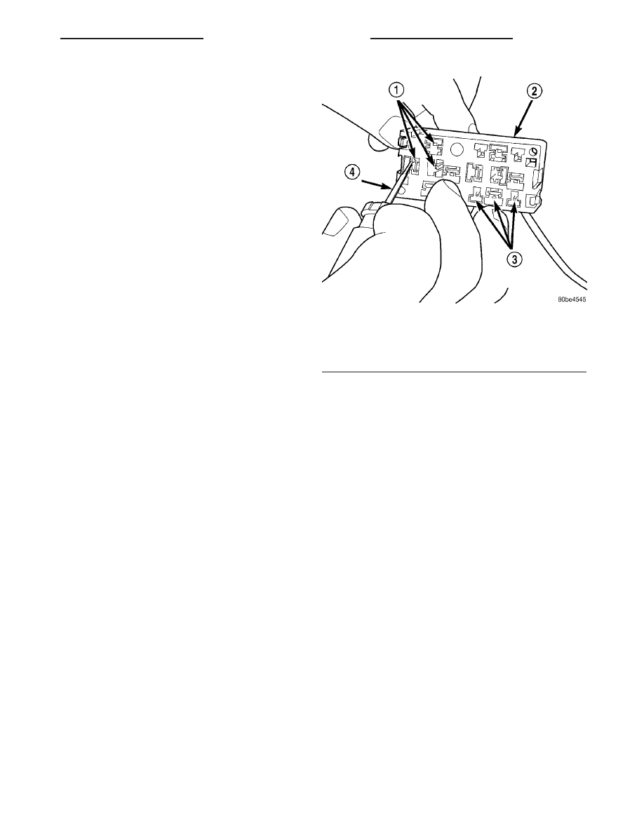
(4) While pulling gently on the wire from the bot-

tom of the faulty PDC relay cassette, use a terminal
pick tool (Special Tool Kit 6680) from the top of the
relay cassette to release the latch that secures the
terminal in the relay cassette terminal cavity (Fig.
15).

(5) From the bottom of the faulty PDC relay cas-

sette, remove the wire and terminal from the relay
cassette terminal cavity.

(6) Make all necessary repairs and splices to the

wire for the removed terminal. Refer to Wiring
Repair 
in the index of this service manual for the
location of the proper wiring repair procedures.

(7) From the bottom of the PDC housing, align and

insert the removed wire and terminal into the correct
terminal cavity of the replacement relay cassette.
Push the wire and terminal up into the relay cassette
terminal cavity until it is fully engaged by the latch.

(8) Repeat Step 4, Step 5, Step 6 and Step 7 one

wire and terminal at a time until each of the wires
and terminals have been transferred from the faulty

PDC relay cassette into the replacement relay cas-
sette.

(9) Install the PDC relay wedge into the replace-

ment PDC relay cassette.

INSTALLATION

The Power Distribution Center (PDC) main hous-

ing unit, the PDC fuse wedges and the PDC bus bars
cannot be repaired and are only serviced as a unit
with the dash wire harness. If the PDC main housing
unit, the fuse wedges or the bus bars are faulty or
damaged, the entire PDC and dash wire harness unit
must be replaced.

NOTE: If the PDC is being replaced with a new unit,
be certain to transfer each of the fuses and relays
that have not been included with the replacement
PDC from the faulty PDC to the proper cavities of
the replacement unit. Refer to Power Distribution in
the index of this service manual for the location of
complete PDC wiring diagrams and cavity assign-
ments.

(1) Position the PDC and the dash wire harness

unit in the engine compartment.

(2) Engage the mounts on the PDC housing with

the stanchions of the PDC bracket and push the unit
downward until the mount latches engage the
mounting tabs on the PDC bracket.

(3) Install the eyelet terminal of the battery posi-

tive cable take out and the engine wire harness gen-

Fig. 15 PDC Relay Cassette Terminal Remove/Install

1 - TERMINAL CAVITIES
2 - PDC RELAY CASSETTE
3 - TERMINAL LATCHES
4 - FROM SPECIAL TOOL KIT 6680

TJ

8W-97 POWER DISTRIBUTION

8W - 97 - 11

POWER DISTRIBUTION CENTER (Continued)

erator output take out onto the PDC B(+) terminal
studs.

(4) Install and tighten the two nuts that secure

the eyelet terminal of the battery positive cable take
out and the engine wire harness generator output
take out to the B(+) terminal studs. Tighten the nuts
to 11.3 N·m (100 in. lbs.).

(5) Engage the tabs on the lower edge of the B(+)

terminal stud cover in the slots on the back of the
PDC housing, then engage the latch on the top of the
cover with the latch receptacle on the PDC housing.

(6) Engage each of the retainers that secure the

dash wire harness to the vehicle body and chassis
components. Refer to Connector Locations in the
index of this service manual for the location of more
information on the dash wire harness retainer loca-
tions.

(7) Install all of the fasteners that secure each of

the dash wire harness ground eyelets to the vehicle
body and chassis components. Refer to Connector
Locations 
in the index of this service manual for the
location of more information on the ground eyelet
locations.

(8) Reconnect each of the dash wire harness con-

nectors. Refer to Connector Locations in the index
of this service manual for the location of more infor-
mation on the dash wire harness connector locations.

(9) Reconnect the battery negative cable.

POWER DISTRIBUTION
CENTER SUPPORT BRACKET

REMOVAL

(1) Disconnect and isolate the battery negative

cable.

(2) Remove the Power Distribution Center (PDC)

from the PDC bracket (Refer to 8 - ELECTRICAL/
POWER DISTRIBUTION/POWER DISTRIBUTION
CENTER - REMOVAL).

(3) Remove the three screws that secure the PDC

bracket to the right front inner fender (Fig. 16).

(4) Remove the PDC bracket from the right front

inner fender.

INSTALLATION

(1) Position the PDC bracket onto the right front

inner fender.

(2) Install and tighten the three screws that secure

the PDC mounting bracket to the right front inner
fender. Tighten the screws to 3.9 N·m (35 in. lbs.).

(3) Install the PDC onto the PDC bracket (Refer to

8 - ELECTRICAL/POWER DISTRIBUTION/POWER
DISTRIBUTION CENTER - INSTALLATION).

(4) Reconnect the battery negative cable.

POWER OUTLET

DESCRIPTION

An instrument panel power outlet is standard fac-

tory installed equipment on this model. The power
outlet is installed in the instrument panel accessory
switch bezel, which is located near the bottom of the
center bezel area below the heater and air condition-
ing controls. The power outlet base is secured by a
snap fit within the instrument panel. A plastic pro-
tective cap snaps into the power outlet base when the
power outlet is not being used, and hangs from the
power outlet base mount by an integral bail strap
while the power outlet is in use.

The power outlet receptacle unit and the accessory

power outlet protective cap are available for service.
The power outlet receptacle cannot be repaired and,
if faulty or damaged, it must be replaced.

OPERATION

The power outlet base or receptacle shell is con-

nected to ground, and an insulated contact in the
bottom of the shell is connected to battery current.
The power outlet receives battery voltage from a fuse
in the Power Distribution Center at all times.

While the power outlet is very similar to a cigar

lighter base unit, it does not include the two small
spring-clip retainers inside the bottom of the recepta-
cle shell that are used to secure the cigar lighter
heating element to the insulated contact.

Fig. 16 PDC Bracket

1 - SCREWS (3)
2 - RIGHT FRONT FENDER
3 - PDC BRACKET

8W - 97 - 12

8W-97 POWER DISTRIBUTION

TJ

POWER DISTRIBUTION CENTER (Continued)

DIAGNOSIS AND TESTING - POWER OUTLET

For complete circuit diagrams, refer to Power

Outlet in Wiring Diagrams.

(1) Check the fused B(+) fuse in the Power Distri-

bution Center. If OK, go to Step 2. If not OK, repair
the shorted circuit or component as required and
replace the faulty fuse.

(2) Check for battery voltage at the fused B(+) fuse

in the Power Distribution Center. If OK, go to Step 3.
If not OK, repair the open fused B(+) circuit to the
battery as required.

(3) Remove the plastic protective cap from the

power outlet receptacle. Check for continuity between
the inside circumference of the power outlet recepta-
cle and a good ground. There should be continuity. If
OK, go to Step 4. If not OK, go to Step 5.

(4) Check for battery voltage at the insulated con-

tact located at the back of the power outlet recepta-
cle. If not OK, go to Step 5.

(5) Disconnect and isolate the battery negative

cable. Remove the power outlet receptacle from the
instrument panel. Disconnect the wire harness con-
nector from the power outlet receptacle. Check for
continuity between the ground circuit cavity of the
power outlet wire harness connector and a good
ground. There should be continuity. If OK, go to Step
6. If not OK, repair the open ground circuit to ground
as required.

(6) Connect the battery negative cable. Check for

battery voltage at the fused B(+) circuit cavity of the
power outlet wire harness connector. If OK, replace
the faulty power outlet receptacle. If not OK, repair
the open fused B(+) circuit to the Power Distribution
Center fuse as required.

REMOVAL

(1) Disconnect and isolate the battery negative

cable.

(2) Pull the cigar lighter knob and element out of

the cigar lighter receptacle base, or unsnap the pro-
tective cap from the power outlet receptacle base.

(3) Look inside the cigar lighter or power outlet

receptacle base and note the position of the rectangu-
lar retaining bosses of the mount that secures the
receptacle base to the instrument panel (Fig. 17).

(4) Insert a pair of external snap ring pliers into

the cigar lighter or power outlet receptacle base and
engage the tips of the pliers with the retaining
bosses of the mount.

(5) Squeeze the pliers to disengage the mount

retaining bosses from the receptacle base and, using
a gentle rocking motion, pull the pliers and the
receptacle base out of the mount.

(6) Pull the receptacle base away from the instru-

ment panel far enough to access the instrument
panel wire harness connector.

(7) Disconnect the instrument panel wire harness

connector from the cigar lighter or power outlet
receptacle base connector receptacle.

(8) Remove the cigar lighter or power outlet mount

from the instrument panel.

INSTALLATION

(1) Reconnect the instrument panel wire harness

connector to the cigar lighter or power outlet recep-
tacle base connector receptacle.

(2) Install the cigar lighter or power outlet mount

into the instrument panel.

(3) Align the splines on the outside of the cigar

lighter or power outlet receptacle base connector
receptacle with the grooves on the inside of the
mount.

(4) Press firmly on the cigar lighter or power out-

let receptacle base until the retaining bosses of the
mount are fully engaged in their receptacles.

(5) Install the cigar lighter knob and element into

the cigar lighter receptacle base, or the protective cap
into the power outlet receptacle base.

(6) Reconnect the battery negative cable.

Fig. 17 Cigar Lighter and Power Outlet Remove/

Install

1 - KNOB AND ELEMENT
2 - RETAINING BOSSES-ENGAGE PLIERS HERE
3 - BASE
4 - PARTIALLY REMOVED
5 - EXTERNAL SNAP-RING PLIERS
6 - MOUNT
7 - BASE

TJ

8W-97 POWER DISTRIBUTION

8W - 97 - 13

POWER OUTLET (Continued)

RELAY

DESCRIPTION

A

relay

is

an

electromechanical

device

that

switches fused battery current to a electrical compo-
nent when the ignition switch is turned to the Acces-
sory or Run positions, or when controlled by a
electronic module. The relays are located in the junc-
tion block or power distribution center (Fig. 18).

The relay is a International Standards Organiza-

tion (ISO) relay. Relays conforming to the ISO speci-
fications have common physical dimensions, current
capacities, terminal patterns, and terminal functions.

A relay cannot be repaired or adjusted and, if

faulty or damaged, it must be replaced.

OPERATION

The ISO relay consists of an electromagnetic coil, a

resistor and three (two fixed and one movable) elec-
trical contacts. The movable (common feed) relay con-
tact is held against one of the fixed contacts
(normally closed) by spring pressure. When the elec-
tromagnetic coil is energized, it draws the movable
contact away from the normally closed fixed contact,
and holds it against the other (normally open) fixed
contact.

When the electromagnetic coil is de-energized,

spring pressure returns the movable contact to the
normally closed position. The resistor is connected in
parallel with the electromagnetic coil in the relay,
and helps to dissipate voltage spikes that are pro-
duced when the coil is de-energized.

DIAGNOSIS AND TESTING - RELAY

The relays are located in the junction block or

power distribution center. For complete circuit dia-
grams, refer to Wiring Diagrams.

(1) Remove the relay from its mounting location.
(2) A relay in the de-energized position should

have continuity between terminals 87A and 30, and
no continuity between terminals 87 and 30. If OK, go
to Step 3. If not OK, replace the faulty relay.

(3) Resistance between terminals 85 and 86 (elec-

tromagnet) should be 60.7 - 80.3 ohms. If OK, go to
Step 4. If not OK, replace the faulty relay.

(4) Connect a battery to terminals 85 and 86.

There should now be continuity between terminals
30 and 87, and no continuity between terminals 87A
and 30. If OK, perform the Relay Circuit Test that
follows. If not OK, replace the faulty relay.

DIAGNOSIS & TESTING - RELAY CIRCUIT TEST

(1) The relay common feed terminal cavity (30) of

the junction block or power distribution center is con-
nected to battery voltage and should be hot at all
times. Check for battery voltage at the fused B(+) cir-
cuit cavity in the junction block receptacle for the
relay. If OK, go to Step 2. If not OK, repair the fused
B(+) circuit to the Power Distribution Center (PDC)
fuse as required.

(2) The relay normally closed terminal (87A) is

connected to terminal 30 in the de-energized position,
but is not used for this application. Go to Step 3.

(3) The relay normally open terminal (87) is con-

nected to the common feed terminal (30) in the ener-
gized position. This terminal supplies battery voltage
to the fused B(+) fuse in the junction block that feeds
the accessory when the relay is energized by the igni-
tion switch. There should be continuity between the
junction block cavity for relay terminal 87 and the
fused B(+) fuse in the junction block at all times. If
OK, go to Step 4. If not OK, repair the open fused
B(+) circuit to the junction block fuse as required.

(4) The coil ground terminal (85) is connected to

the electromagnet in the relay. It receives battery
feed to energize the relay when the ignition switch is
in the Accessory or Run positions. Turn the ignition
switch to the On position. Check for battery voltage
at the fused ignition switch output (acc/run) circuit
cavity for relay terminal 85 in the junction block
receptacle for the relay. If OK, go to Step 5. If not
OK, repair the open fused ignition switch output
(acc/run) circuit to the ignition switch as required.

(5) The coil battery terminal (86) is connected to

the electromagnet in the relay. The junction block
cavity for this terminal should have continuity to
ground at all times. If not OK, repair the open
ground circuit to ground as required.

Fig. 18 ISO Relay

30 - COMMON FEED
85 - COIL GROUND
86 - COIL BATTERY
87 - NORMALLY OPEN
87A - NORMALLY CLOSED

8W - 97 - 14

8W-97 POWER DISTRIBUTION

TJ


Content   ..  418  419  420  421   ..