Jeep Wrangler TJ. Manual - part 418


  Index      Jeep     Jeep Wrangler TJ - service repair manual 2005 year


Search            


Content   ..  416  417  418  419   ..


Jeep Wrangler TJ. Manual - part 418


shell. If OK, replace the faulty cigar lighter knob and
element. If not OK, go to Step 3.

(3) Turn the ignition switch to the Off position.

Disconnect and isolate the battery negative cable.
Remove the instrument panel accessory switch bezel.
Check for continuity between the ground circuit cav-
ity #3 of the cigar lighter wire harness connector and
a good ground. There should be continuity. If OK, go
to Step 4. If not OK, repair the open ground circuit to
ground as required.

(4) Connect the battery negative cable. Turn the

ignition switch to the Accessory or On positions.
Check for battery voltage at cavity #1 of the cigar
lighter wire harness connector. If OK, replace the
faulty accessory switch bezel unit. If not OK, check
for blown fuse in the fuseblock (f19) or in the PDC
(f13). If fuse is blown check for short circuit. Repair
the circuit as required and replace blown fuse.

FUSE BLOCK

DESCRIPTION

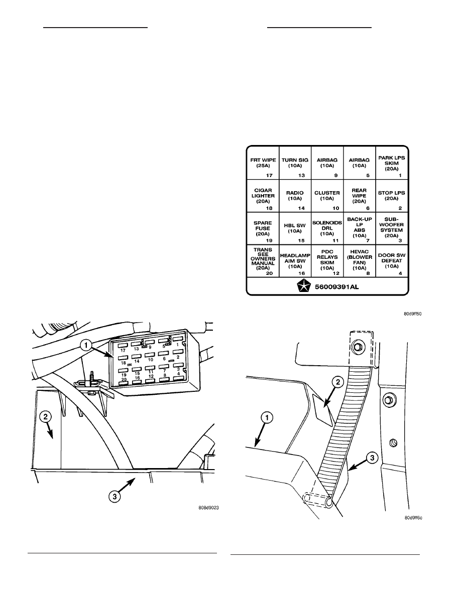
An electrical fuseblock module is mounted on the

dash panel in the passenger compartment of the
vehicle (Fig. 1). The fuseblock module serves to dis-
tribute electrical current to many of the accessory
systems in the vehicle. The fuseblock module houses
up to twenty blade-type mini fuses.

The molded plastic fuseblock module housing has

an integral mounting bracket that is secured with
two screws to a bracket welded on the dash panel
just above the heater and air conditioner housing.
The glove box is rolled down from the instrument
panel for service access of the fuseblock module
fuses. An adhesive-backed fuse layout map (Fig. 2)is
located on the outside of the glove box bin (Fig. 3) to
ensure proper fuse identification.

Fig. 1 Fuseblock Module Location

1 - FUSE BLOCK
2 - HEATER CASE
3 - GLOVE BOX OPENING

Fig. 2 Fuseblock Label

Fig. 3 Fuseblock Label Location

1 - GLOVE BOX DOOR
2 - FUSEBLOCK LABEL
3 - GLOVE BOX BIN

TJ

8W-97 POWER DISTRIBUTION

8W - 97 - 3

CIGAR LIGHTER OUTLET (Continued)

The fuseblock module is integral to the body wire

harness. If any internal circuit or the fuseblock mod-
ule housing is faulty or damaged, the entire fuse-
block module and body harness unit must be
replaced.

OPERATION

All of the circuits entering and leaving the fuse-

block module do so through the body wire harness.
Internal connection of all of the fuseblock module cir-
cuits is accomplished by an intricate combination of
hard wiring and bus bars. Refer to Wiring Dia-
grams 
for the location of complete fuseblock module
circuit diagrams.

REMOVAL

The fuseblock module is serviced as a unit with the

body wire harness. If any internal circuit of the fuse-
block module or if the fuseblock module housing is
faulty or damaged, the entire fuseblock module and
the body wire harness unit must be replaced.

(1) Disconnect and isolate the battery negative

cable.

(2) Remove the instrument panel assembly from

the dash panel (Refer to 23 - BODY/INSTRUMENT
PANEL/INSTRUMENT

PANEL

ASSEMBLY

-

REMOVAL).

(3) Disconnect each of the body wire harness con-

nectors. Refer to Connector Locations in Wiring
for the location of the body wire harness connector
locations.

(4) Remove all of the fasteners that secure each of

the body wire harness ground eyelets to the vehicle
body and chassis components. Refer to Connector
Locations 
in Wiring for the location of the body wire
harness ground locations.

(5) Disengage each of the retainers that secure the

body wire harness to the vehicle body and chassis
components. Refer to Connector Locations in Wir-
ing for the location of the body wire harness retainer
locations.

(6) Remove the two screws that secure the fuse-

block module to the bracket on the dash panel (Fig.
4).

(7) Remove the fuseblock module and the body

wire harness from the dash panel as a unit.

INSTALLATION

The fuseblock module is serviced as a unit with the

body wire harness. If any internal circuit of the fuse-
block module or if the fuseblock module housing is
faulty or damaged, the entire fuseblock module and
the body wire harness unit must be replaced.

NOTE: If the fuseblock module is being replaced
with a new unit, be certain to transfer each of the

fuses from the faulty fuseblock module to the
proper cavities of the replacement fuseblock mod-
ule. Refer to Fuse/Fuse Block in the index of this
service manual for the location of complete fuse-
block module circuit diagrams and cavity assign-
ments.

(1) Position the fuseblock module and the body

wire harness onto the dash panel as a unit.

(2) Install and tighten the two screws that secure

the fuseblock module to the bracket on the dash
panel. Tighten the screws to 3.3 N·m (30 in. lbs.).

(3) Engage each of the retainers that secure the

body wire harness to the vehicle body and chassis
components. Refer to Connector Locations in Wir-
ing for the location of the body wire harness retainer
locations.

(4) Install all of the fasteners that secure each of

the body wire harness ground eyelets to the vehicle
body and chassis components. Refer to Connector
Locations 
in Wiring for the location of the body wire
harness ground eyelet locations.

(5) Reconnect each of the body wire harness con-

nectors. Refer to Connector Locations in Wiring
for the location of the body wire harness connector
locations.

(6) Install the instrument panel assembly onto the

dash panel (Refer to 23 - BODY/INSTRUMENT PAN-
EL/INSTRUMENT PANEL ASSEMBLY - INSTAL-
LATION).

(7) Reconnect the battery negative cable.

Fig. 4 Fuseblock Module Remove/Install

1 - BODY WIRE HARNESS
2 - BRACKET
3 - FUSEBLOCK MODULE
4 - SCREWS (2)

8W - 97 - 4

8W-97 POWER DISTRIBUTION

TJ

FUSE BLOCK (Continued)

IOD FUSE

DESCRIPTION

All vehicles are equipped with an Ignition-Off

Draw (IOD) fuse (Fig. 5) that is removed from its
cavity in the Power Distribution Center (PDC) when
the vehicle is shipped from the factory. Dealer per-
sonnel are to remove the IOD fuse from the storage
location and install it into PDC fuse cavity 15 as part
of the preparation procedures performed just prior to
new vehicle delivery.

The PDC has a molded plastic cover that can be

unlatched and opened to provide service access to all
of the fuses and relays in the PDC. An integral latch
and hinge tabs are molded into the PDC cover for
easy removal. A fuse layout map is integral to the
underside of the PDC cover to ensure proper fuse
and relay identification. The IOD fuse is a 50 ampere
cartridge-type fuse and, when removed, it is stored in
the empty fuse cavity 11 of the PDC.

OPERATION

The term ignition-off draw identifies a normal con-

dition where power is being drained from the battery
with the ignition switch in the Off position. The IOD
fuse feeds the memory and sleep mode functions for
many of the electronic modules in the vehicle as well
as various other accessories that require battery cur-
rent when the ignition switch is in the Off position,

including the clock. The only reason the IOD fuse is
removed is to reduce the normal IOD of the vehicle
electrical system during new vehicle transportation
and pre-delivery storage to reduce battery depletion,
while still allowing vehicle operation so that the
vehicle can be loaded, unloaded and moved as needed
by both vehicle transportation company and dealer
personnel.

The IOD fuse is removed from PDC fuse cavity #15

when the vehicle is shipped from the assembly plant.
Dealer personnel must install the IOD fuse when the
vehicle is being prepared for delivery in order to
restore full electrical system operation. Once the
vehicle is prepared for delivery, the IOD function of
this fuse becomes transparent and the fuse that has
been assigned the IOD designation becomes only
another Fused B(+) circuit fuse. The IOD fuse serves
no useful purpose to the dealer technician in the ser-
vice or diagnosis of any vehicle system or condition,
other than the same purpose as that of any other
standard circuit protection device.

The IOD fuse can be used by the vehicle owner as

a convenient means of reducing battery depletion
when a vehicle is to be stored for periods not to
exceed about thirty days. However, it must be
remembered that removing the IOD fuse will not
eliminate IOD, but only reduce this normal condition.
If a vehicle will be stored for more than about thirty
days, the battery negative cable should be discon-
nected to eliminate normal IOD; and, the battery
should be tested and recharged at regular intervals
during the vehicle storage period to prevent the bat-
tery from becoming discharged or damaged.

REMOVAL

The Ignition-Off Draw (IOD) fuse is removed from

Power Distribution Center (PDC) fuse cavity #15
when the vehicle is shipped from the assembly plant.
Dealer personnel must install the IOD fuse when the
vehicle is being prepared for delivery in order to
restore full electrical system operation.

(1) Turn the ignition switch to the Off position.
(2) Unlatch and open the cover from the PDC.
(3) Remove the IOD fuse from fuse cavity #15 of

the PDC.

(4) Store the removed IOD fuse by inserting the

terminal blades of the fuse into the empty fuse cavity
#11 of the PDC.

(5) Close and latch the cover onto the PDC.

INSTALLATION

The Ignition-Off Draw (IOD) fuse is removed from

Power Distribution Center (PDC) fuse cavity #15
when the vehicle is shipped from the assembly plant.
Dealer personnel must install the IOD fuse when the

Fig. 5 Ignition-Off Draw Fuse

1 - IGNITION-OFF DRAW FUSE
2 - IGNITION-OFF DRAW FUSE STORAGE LOCATION
3 - POWER DISTRIBUTION CENTER

TJ

8W-97 POWER DISTRIBUTION

8W - 97 - 5

vehicle is being prepared for delivery in order to
restore full electrical system operation.

(1) Turn the ignition switch to the Off position.
(2) Unlatch and open the cover from the PDC.
(3) Remove the stored IOD fuse from fuse cavity

#11 of the PDC.

(4) Align the terminal blades of the IOD fuse with

the terminal receptacles in fuse cavity #15 of the
PDC.

(5) Use a thumb to press the IOD fuse firmly down

into PDC fuse cavity #15.

(6) Close and latch the cover onto the PDC.

MICRO-RELAY

DESCRIPTION

A micro-relay is a conventional International Stan-

dards Organization (ISO) micro relay (Fig. 6). Relays
conforming to the ISO specifications have common
physical dimensions, current capacities, terminal pat-
terns, and terminal functions. The relay is contained
within a small, rectangular, molded plastic housing
and is connected to all of the required inputs and
outputs by five integral male spade-type terminals
that extend from the bottom of the relay base.

Relays cannot be adjusted or repaired and, if faulty

or damaged, the unit must be replaced.

OPERATION

A micro-relay is an electromechanical switch that

uses a low current input from one source to control a
high current output to another device. The movable
common feed contact point is held against the fixed

normally closed contact point by spring pressure.
When the relay coil is energized, an electromagnetic
field is produced by the coil windings. This electro-
magnetic field draws the movable relay contact point
away from the fixed normally closed contact point,
and holds it against the fixed normally open contact
point. When the relay coil is de-energized, spring
pressure returns the movable contact point back
against the fixed normally closed contact point. A
resistor is connected in parallel with the relay coil in
the relay, and helps to dissipate voltage spikes and
electromagnetic interference that can be generated as
the electromagnetic field of the relay coil collapses.

DIAGNOSIS AND TESTING - MICRO-RELAY

(1) Remove the relay from its mounting location.
(2) A relay in the de-energized position should

have continuity between terminals 87A and 30, and
no continuity between terminals 87 and 30 (Fig. 6). If
OK, go to Step 3. If not OK, replace the faulty relay.

(3) Resistance between terminals 85 and 86 (elec-

tromagnet) should be 67.5 - 82.5 ohms. If OK, go to
Step 4. If not OK, replace the faulty relay.

(4) Connect a battery to terminals 85 and 86.

There should now be continuity between terminals
30 and 87, and no continuity between terminals 87A
and 30. If OK, reinstall the relay and use a DRBIII

t

scan tool to perform further testing. Refer to the
appropriate diagnostic information.

Refer to the appropriate wiring information. The

wiring information includes wiring diagrams, proper
wire and connector repair procedures, details of wire
harness routing and retention, connector pin-out
information and location views for the various wire
harness connectors, splices and grounds.

REMOVAL

(1) Disconnect and isolate the negative battery

cable.

(2) Remove the relay by grasping it firmly and

pulling it straight out from its receptacle. A slight
back and fourth rocking motion may help the
removal process.

INSTALLATION

(1) Align the micro-relay terminals with the termi-

nal cavities in the receptacle.

(2) Push firmly and evenly on the top of the relay

until the terminals are fully seated in the terminal
cavities in the receptacle.

(3) Connect the battery negative cable.

Fig. 6 ISO Micro Relay

30 - COMMON FEED
85 - COIL GROUND
86 - COIL BATTERY
87 - NORMALLY OPEN
87A - NORMALLY CLOSED

8W - 97 - 6

8W-97 POWER DISTRIBUTION

TJ

IOD FUSE (Continued)


Content   ..  416  417  418  419   ..