Jeep Wrangler TJ. Manual - part 335


  Index      Jeep     Jeep Wrangler TJ - service repair manual 2005 year


Search            


Content   ..  333  334  335  336   ..


Jeep Wrangler TJ. Manual - part 335


(4) Using a trim stick or another suitable wide

flat-bladed tool, gently pry the barbed inlet nipple of
the front washer pump/motor out of the rubber grom-
met seal in the washer reservoir. Care must be taken
not to damage the washer reservoir.

(5) Remove the front washer pump/motor from the

washer reservoir.

(6) Remove the rubber grommet seal from the

front washer pump/motor mounting hole in the
washer reservoir and discard.

INSTALLATION

(1) Install a new rubber grommet seal into the

front washer pump/motor mounting hole of the
washer reservoir.

(2) Position the front washer pump/motor inlet

nipple to the mounting hole in the washer reservoir
(Fig. 11).

(3) Using hand pressure, firmly and evenly press

on the front washer pump/motor to engage the inlet
nipple through the rubber grommet seal and into the
washer reservoir. Care must be taken not to damage
the washer reservoir.

(4) Reconnect the headlamp and dash wire harness

connector for the front washer pump/motor to the
washer pump/motor connector receptacle.

(5) Reconnect the front washer supply hose to the

barbed outlet nipple of the front washer pump/motor.

(6) Refill the washer reservoir with the washer

fluid drained from the reservoir during the removal
procedure.

(7) Reconnect the battery negative cable.

FRONT WIPER ARM

DESCRIPTION

The front wiper arms are the rigid members

located between the wiper pivots that protrude from
the cowl plenum cover/grille panel near the base of
the windshield and the wiper blades on the wind-
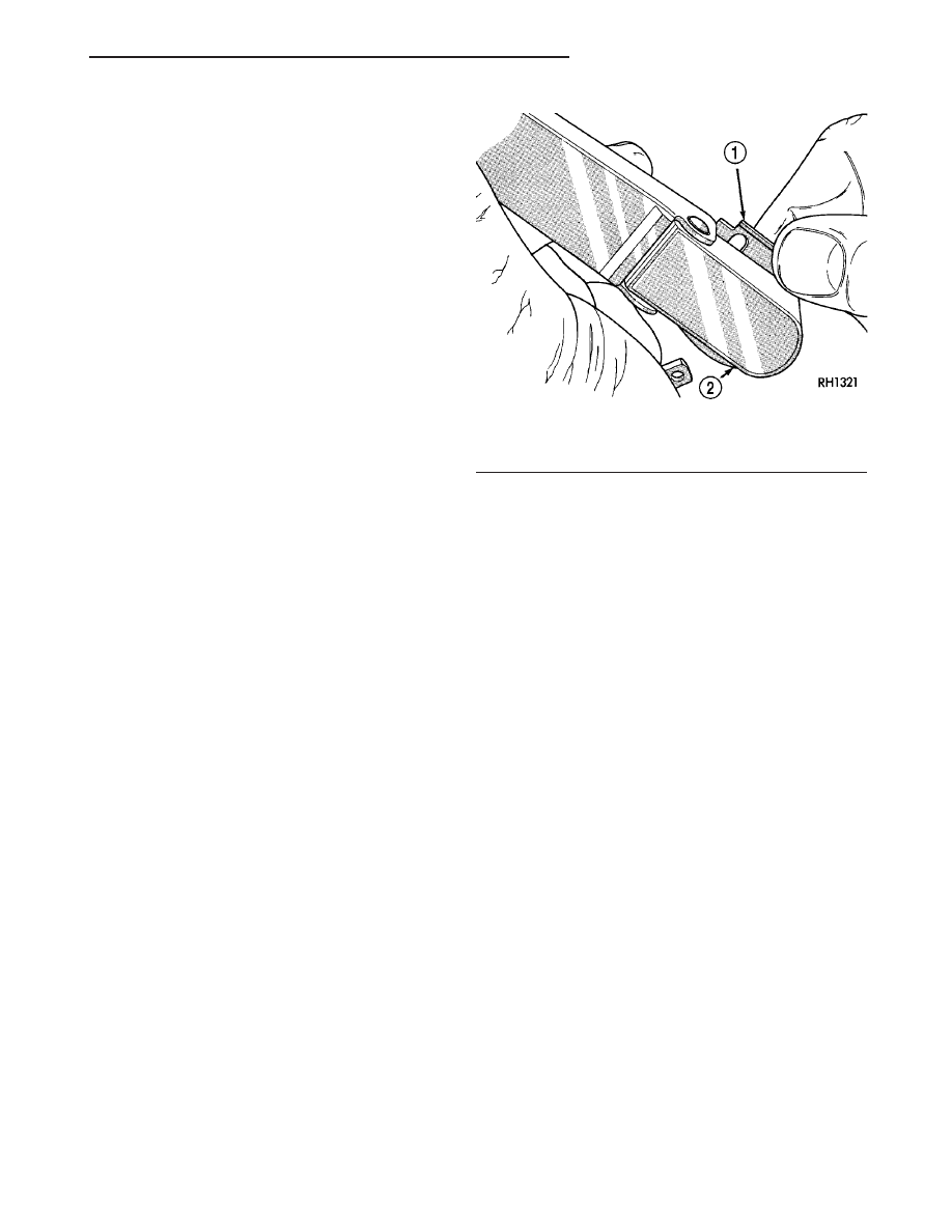
shield glass. The wiper arm has a die cast metal
pivot end (Fig. 12). On the underside of this pivot
end is a large internally serrated socket formation
with a small, movable, stamped steel latch plate that
is secured loosely under a small strap that is staked
to the pivot end.

The wide end of a tapered, stamped steel channel

hinges on and is secured with a hinge pin to the
pivot end of the wiper arm. One end of a long, rigid,
stamped steel strap, with a small hole near its pivot
end, is riveted and crimped within the narrow end of
the stamped steel channel. The tip of the wiper blade
end of this strap is bent back under itself to form a
small hook. Concealed within the stamped steel
channel, one end of a long spring is hooked through a

hole in a small stamped steel strap on the hinge pin
within the die cast pivot end, while the other end of
the spring is hooked through the small hole in the
steel strap. The entire wiper arm has a satin black
finish applied to all of its visible surfaces.

A wiper arm cannot be adjusted or repaired. If

damaged or faulty, the entire wiper arm unit must be
replaced.

OPERATION

The front wiper arms are designed to mechanically

transmit the motion from the wiper pivots to the
wiper blades. The wiper arm must be properly
indexed to the wiper pivot in order to maintain the
proper wiper blade travel on the glass. The serrated
socket formation in the wiper arm pivot end inter-
locks with the serrations on the outer circumference
of the wiper pivot driver, providing positive engage-
ment and finite adjustment of this connection. The
latch plate on the underside of the wiper arm pivot
end locks the wiper arm to the wiper pivot driver
when in its installed position; and, when in its
unlocked position, also serves as a blocker to hold the
spring-loaded wiper arm off of the glass to facilitate
removal and installation. The spring-loaded wiper
arm hinge controls the down-force applied through
the tip of the wiper arm to the wiper blade on the
glass. The hook formation on the tip of the wiper arm
provides a cradle for securing and latching the wiper
blade pivot block to the wiper arm.

REMOVAL

(1) Lift the front wiper arm far enough to raise the

wiper blade off of the glass and permit the wiper arm
latch plate to be pulled out to its holding position,
then release the arm (Fig. 13). The wiper arm and

Fig. 12 Wiper Arm

1 - LATCH
2 - WIPER ARM PIVOT END

TJ

FRONT WIPERS/WASHERS

8R - 13

FRONT WASHER PUMP MOTOR (Continued)

blade will remain off the glass with the latch in this
position.

CAUTION: The use of a screwdriver or other prying
tool to remove a wiper arm may distort it. This dis-
tortion could allow the arm to come off of the wiper
pivot during wiper operation, regardless of how
carefully it is reinstalled.

(2) Using a slight rocking motion, remove the front

wiper arm pivot end from the wiper pivot driver.

INSTALLATION

NOTE: Be certain that the wiper motor is in the park
position before attempting to install the wiper arms.
Turn the ignition switch to the On position and
move the right multi-function switch control stalk to
its Off position. If the wiper pivots move, wait until
they stop moving, then turn the ignition switch
back to the Off position. The wiper motor is now in
its park position.

(1) The front wiper arms must be indexed to the

wiper pivots with the wiper motor in the park posi-
tion to be properly installed (Fig. 14). Position the
front wiper arm pivot ends onto the wiper pivot driv-
ers so that the tip of the wiper blade is on the upper
edge of the lower windshield blackout area, + 15 mil-
limeters/– 0 millimeter (+ 0.59 inch/– 0 inch).

(2) Once the wiper arm is indexed to the wiper

pivot, lift the wiper arm away from the windshield
slightly to relieve the spring tension on the latch
plate, then push the latch into the locked position
(Fig. 13). Gently lower the wiper arm until the wiper
blade is in position on the windshield glass.

(3) Wet the windshield glass, then operate the

front wipers. Move the right multi-function switch
control stalk to the Off position, then check for cor-
rect wiper arm position. Repeat the adjustment as
required.

FRONT WIPER BLADE

DESCRIPTION

Each front wiper blade is secured by an integral

latching pivot block to the hook formation on the tip
of each front wiper arm, and rests on the glass near
the base of the windshield when the wipers are not
in operation (Fig. 15). The wiper blade consists of the
following components:

• Superstructure - The superstructure includes

several stamped steel bridges and links with claw
formations that grip the wiper blade element. Also
included in this unit is the latching, molded plastic
pivot block that secures the superstructure to the
wiper arm. All of the metal components of the wiper
blade have a satin black finish applied.

Fig. 13 Front Wiper Arm Remove/Install

1 - LATCH
2 - WIPER ARM PIVOT END

Fig. 14 Front Wiper Arm Installation

1 - WINDSHIELD BLACKOUT AREA
2 - PARK BLADE ON UPPER EDGE OF BLACKOUT AREA
+15 mm – 0 mm (+0.59 in. – 0 in.)

Fig. 15 Wiper Blade - Typical

1 - RELEASE TAB

8R - 14

FRONT WIPERS/WASHERS

TJ

FRONT WIPER ARM (Continued)

• Element - The wiper element or squeegee is the

resilient rubber member of the wiper blade that con-
tacts the glass.

• Flexor - The flexor is a rigid metal component

running along the length of each side of the wiper
element where it is gripped by the claws of the
superstructure.

All models have two 33-centimeter (13-inch) long

front wiper blades with non-replaceable rubber ele-
ments (squeegees). The wiper blades cannot be
adjusted or repaired. If faulty, worn, or damaged the
entire wiper blade unit must be replaced.

OPERATION

The wiper blades are moved back and forth across

the glass by the wiper arms when the wipers are
being operated. The wiper blade superstructure is
the flexible frame that grips the wiper blade element
and evenly distributes the force of the spring-loaded
wiper arm along the length of the element. The com-
bination of the wiper arm force and the flexibility of
the superstructure makes the element conform to
and maintain proper contact with the glass, even as
the blade is moved over the varied curvature that
may be encountered across the glass surface. The
wiper element flexor provides the claws of the blade
superstructure with a rigid, yet flexible component
on the element which can be gripped. The rubber ele-
ment is designed to be stiff enough to maintain an
even cleaning edge as it is drawn across the glass,
yet resilient enough to conform to the glass surface
and flip from one cleaning edge to the other each
time the wiper blade changes directions.

REMOVAL

NOTE: The notched end of the wiper element flexor
should always be oriented towards the end of the
wiper blade that is nearest to the wiper pivot.

(1) Lift the front wiper arm to raise the wiper

blade and element off of the glass.

(2) To remove the wiper blade from the wiper arm,

depress the pivot block latch release tab under the
tip of the arm and slide the blade away from the tip
towards the pivot end of the arm far enough to dis-
engage the pivot block from the hook formation on
the end of the arm (Fig. 16).

(3) Extract the hook formation on the tip of the

wiper arm through the opening in the wiper blade
superstructure just ahead of the wiper blade pivot
block/latch unit.

CAUTION: Do not allow the wiper arm to spring
back against the glass without the wiper blade in
place or the glass may be damaged.

(4) Gently lower the tip of the wiper arm onto the

glass.

INSTALLATION

NOTE: The notched end of the wiper element flexor
should always be oriented towards the end of the
wiper blade that is nearest to the wiper pivot.

(1) Lift the front wiper arm off of the windshield

glass.

(2) Position the front wiper blade near the hook

formation on the tip of the arm with the notched end
of the wiper element flexor oriented towards the end
of the wiper arm that is nearest to the wiper pivot.

(3) Insert the hook formation on the tip of the

wiper arm through the opening in the wiper blade
superstructure ahead of the wiper blade pivot block/
latch unit far enough to engage the pivot block into
the hook (Fig. 16).

(4) Slide the wiper blade pivot block/latch up into

the hook formation on the tip of the wiper arm until
the latch release tab snaps into its locked position.
Latch engagement will be accompanied by an audible
click.

(5) Gently lower the wiper blade onto the glass.

FRONT WIPER MODULE

DESCRIPTION

The front wiper module is secured with three

screws, one each at the motor bracket and the two
pivot brackets through rubber insulators to the cowl
top panel and concealed within the cowl plenum area
beneath the cowl plenum cover/grille panel (Fig. 17).
The driver ends of the wiper pivot shafts that pro-
trude through dedicated openings in the cowl plenum
cover/grille panel to drive the wiper arms and blades
are the only visible components of the front wiper
module. The front wiper module consists of the fol-
lowing major components:

Fig. 16 Wiper Blade Remove/Install - Typical

1 - RELEASE TAB

TJ

FRONT WIPERS/WASHERS

8R - 15

FRONT WIPER BLADE (Continued)

• Bracket - The front wiper module bracket con-

sists of a long tubular steel main member that has a
stamped pivot bracket formation near each end
where the two wiper pivots are secured. A stamped
steel mounting plate for the wiper motor is secured
with welds near the center of the main member. The
bracket includes metal-sleeved rubber isolators at
each of the three bracket mounting points.

• Crank Arm - The front wiper motor crank arm

is a stamped steel unit with a slotted hole on the
driven end that is secured to the wiper motor output
shaft with a nut, and has a ball stud secured to the
drive end.

• Linkage - The two front wiper linkage members

are each constructed of stamped steel. A connecting
link with a plastic socket-type bushing in each end is
fit over the pivot ball studs to join the two pivots.
The wiper drive link has a plastic socket-type bush-
ing on each end. One end of the drive link is snap-fit
over a second ball stud on the passenger side pivot
crank arm, while the other end is snap-fit over the
ball stud on the wiper motor crank arm.

• Motor - The front wiper motor is secured with

three screws to the motor mounting plate near the
center of the wiper module bracket and is protected
by a rubber boot. The wiper motor output shaft
passes through a hole in the module bracket, where a
nut secures the wiper motor crank arm to the motor
output shaft. The two-speed permanent magnet

wiper motor features an integral transmission, an
internal park switch, and an internal automatic
resetting circuit breaker.

• Pivots - The two front wiper pivots are secured

to the ends of the wiper module bracket. A crank arm
extends from the lower end of each pivot shaft. The
driver side pivot crank arm has a single ball stud
secured to it, while the passenger side crank arm has
two ball studs. The upper end of each pivot shaft
where the wiper arms will be fastened each has an
externally serrated drum-like driver secured to it.

The front wiper module for this model is serviced

only as a complete unit. If any linkage component or
the mounting bracket of the module is faulty or dam-
aged, the entire front wiper module unit must be
replaced. The front wiper motor and boot are avail-
able for service replacement as a unit only.

OPERATION

The front wiper module operation is controlled by

the battery current inputs received by the wiper
motor through the right multi-function switch on the
steering column. The wiper motor is connected to the
vehicle electrical system through a dedicated take
out and wire harness connector of the body wire har-
ness. The wiper motor speed is controlled by current
flow to either the low speed or the high speed set of
brushes. The park switch is a single pole, single
throw, momentary switch within the wiper motor
that is mechanically actuated by the wiper motor
transmission components. The park switch alter-
nately closes the wiper park switch sense circuit to
ground or to battery current, depending upon the
position of the wipers on the glass. This feature
allows the motor to complete its current wipe cycle
after the wiper system has been turned Off, and to
park the wiper blades in the lowest portion of the
wipe pattern. The automatic resetting circuit breaker
protects the motor from overloads. The wiper motor
crank arm, the two wiper linkage members, and the
two wiper pivots mechanically convert the rotary out-
put of the wiper motor to the back and forth wiping
motion of the wiper arms and blades on the glass.

REMOVAL

(1) Remove the front wiper arms from the wiper

pivots. (Refer to 8 - ELECTRICAL/FRONT WIPERS/
WASHERS/FRONT WIPER ARM - REMOVAL).

(2) Unlatch, open and support the hood.
(3) Disconnect and isolate the battery negative

cable.

(4) Remove the cowl plenum cover/grille panel

from over the cowl plenum. (Refer to 23 - BODY/EX-
TERIOR/COWL

GRILLE

AND

SCREEN

-

REMOVAL).

Fig. 17 Front Wiper Module

1 - SCREW (3)
2 - MODULE BRACKET
3 - WIRE HARNESS CONNECTOR
4 - WIPER MOTOR

8R - 16

FRONT WIPERS/WASHERS

TJ

FRONT WIPER MODULE (Continued)


Content   ..  333  334  335  336   ..