Jeep Wrangler TJ. Manual - part 317


  Index      Jeep     Jeep Wrangler TJ - service repair manual 2005 year


Search            


Content   ..  315  316  317  318   ..


Jeep Wrangler TJ. Manual - part 317


(3) Install the screws that secure the dome lamp

housing to the speaker housing.

NOTE: The dome lamp lens is equipped with a
locating tab that must be inserted into the slot in
the dome lamp housing.

(4) Align the dome lamp lens locating tab with the

slot in the dome lamp housing and press the lens
into place.

(5) Reconnect the negative battery cable.

DOME LAMP

REMOVAL

(1) Disconnect the negative battery cable.
(2) Insert a small flat blade between the dome

lamp housing and dome lamp lens. Carefully pry the
lamp lens from the lamp housing

(3) Remove the dome lamp from the lamp termi-

nals by pulling the lamp straight out.

INSTALLATION

(1) Install the dome lamp into the lamp terminals

by pushing the lamp straight into the terminals.

NOTE: The dome lamp lens is equipped with a
locating tab that must be inserted into the slot in
the dome lamp housing.

(2) Align the dome lamp lens locating tab with the

slot in the dome lamp housing and press the lens
into place.

(3) Reconnect the negative battery cable.

DOOR AJAR SWITCH

DESCRIPTION

The door ajar switches, located in each door pillar,

are a self-adjusting, spring loaded plunger. The other
end of the switch is actuated by the hinge face of the
door. The self adjusting feature of the switch plunger
is a one-time feature, it can be adjusted inward (com-
pressed),

but

cannot

be

readjusted

outward

(extended) once it has been compressed. This nor-
mally open switch only closes when the door is open.

The door ajar switch cannot be repaired and, if

faulty or damaged, it must be replaced.

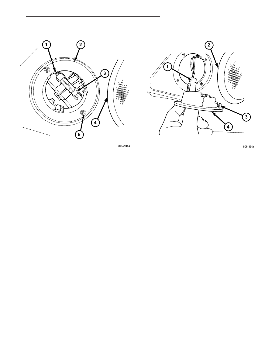
Fig. 1 Dome Lamp - Typical

1 - DOME LENS GUIDE
2 - DOME LAMP HOUSING
3 - DOME LAMP
4 - SPEAKER HOUSING
5 - SCREW (2)

Fig. 2 Dome Lamp Housing

1 - WIRE HARNESS CONNECTOR
2 - SPEAKER
3 - LOCATING TAB
4 - DOME LAMP HOUSING

TJ

LAMPS/LIGHTING - INTERIOR

8L - 33

DOME LAMP UNIT (Continued)

OPERATION

The door ajar switches control a path to ground

through separate driver and passenger door ajar
switch sense circuit inputs to the instrument cluster
chime warning circuitry when a door is opened. The
door ajar switch inputs to the instrument cluster can
be diagnosed using conventional diagnostic tools and
methods.

DIAGNOSIS AND TESTING - DOOR AJAR
SWITCH

WARNING: ON VEHICLES EQUIPPED WITH AIR-
BAGS, DISABLE THE AIRBAG SYSTEM BEFORE
ATTEMPTING ANY STEERING WHEEL, STEERING
COLUMN, OR INSTRUMENT PANEL COMPONENT
DIAGNOSIS OR SERVICE. DISCONNECT AND ISO-
LATE THE BATTERY NEGATIVE (GROUND) CABLE,
THEN WAIT TWO MINUTES FOR THE AIRBAG SYS-
TEM CAPACITOR TO DISCHARGE BEFORE PER-
FORMING FURTHER DIAGNOSIS OR SERVICE. THIS
IS THE ONLY SURE WAY TO DISABLE THE AIRBAG
SYSTEM. FAILURE TO TAKE THE PROPER PRE-
CAUTIONS COULD RESULT IN ACCIDENTAL AIR-
BAG DEPLOYMENT AND POSSIBLE PERSONAL
INJURY.

(1) Disconnect the negative battery cable. Remove

the door ajar switch from the door hinge pillar. Dis-
connect the wire harness connector from the door
ajar switch. Check for continuity between the door
ajar switch output and the driver or passenger door
ajar switch sense circuit in the door ajar switch con-
nector. There should be continuity with the switch
plunger released, and no continuity with the switch
plunger depressed. If OK, go to Step 2. If not OK,
replace the faulty door ajar switch.

(2) Check for continuity between the door ajar

switch output circuit of the wire harness connector
for the driver or passenger door ajar switch and a
good ground. There should be continuity. If OK, go to
Step 3. If not OK, repair the open door ajar switch
output circuit to ground as required.

(3) Remove the instrument cluster from the instru-

ment panel. Disconnect the instrument panel wire
harness

connector

from

the

instrument

cluster.

Check for continuity between the driver or passenger
door ajar switch sense circuit of the wire harness
connector for the driver or passenger door ajar switch
and a good ground. There should be no continuity. If
OK, go to Step 4. If not OK, repair the shorted driver
or passenger door ajar switch sense circuit between
the door ajar switch and the instrument cluster as
required.

(4) Check for continuity between the driver or pas-

senger door ajar switch sense circuit of the wire har-

ness connector for the driver or passenger door ajar
switch and the wire harness connector for the instru-
ment cluster. There should be continuity. If not OK,
repair the open driver or passenger door ajar switch
sense circuit between the door ajar switch and the
instrument cluster as required.

REMOVAL

WARNING: ON VEHICLES EQUIPPED WITH AIR-
BAGS, DISABLE THE AIRBAG SYSTEM BEFORE
ATTEMPTING ANY STEERING WHEEL, STEERING
COLUMN, OR INSTRUMENT PANEL COMPONENT
DIAGNOSIS OR SERVICE. DISCONNECT AND ISO-
LATE THE BATTERY NEGATIVE (GROUND) CABLE,
THEN WAIT TWO MINUTES FOR THE AIRBAG SYS-
TEM CAPACITOR TO DISCHARGE BEFORE PER-
FORMING FURTHER DIAGNOSIS OR SERVICE. THIS
IS THE ONLY SURE WAY TO DISABLE THE AIRBAG
SYSTEM. FAILURE TO TAKE THE PROPER PRE-
CAUTIONS COULD RESULT IN ACCIDENTAL AIR-
BAG DEPLOYMENT AND POSSIBLE PERSONAL
INJURY.

(1) Disconnect the negative battery cable
(2) Unlatch and open the door fully.
(3) Using

a

small

screwdriver,

pry

carefully

between the hinge pillar and the outer circumference
of the door ajar switch housing to release the switch
snap features from the mounting hole in the pillar.

(4) Pull the door ajar switch out through the

mounting hole in the hinge pillar far enough to
access and disconnect the wire harness connector
from the door ajar switch.

(5) Remove the door ajar switch from the door

hinge pillar.

INSTALLATION

(1) Position the door ajar switch to the door hinge

pillar.

(2) Connect the wire harness connector to the door

ajar switch.

(3) Guide the wire harness for the door ajar switch

and the receptacle end of the switch into the mount-
ing hole in the door hinge pillar.

(4) Using hand pressure, press the door ajar

switch housing into the mounting hole in the door
hinge pillar until the snap features of the switch are
fully engage in the mounting hole.

(5) Slowly close the door and allow the door ajar

switch plunger self-adjuster mechanism to ratchet to
the proper position.

(6) Reconnect the negative battery cable.
(7) Open and close the door to verify proper door

ajar switch operation.

8L - 34

LAMPS/LIGHTING - INTERIOR

TJ

DOOR AJAR SWITCH (Continued)

REAR WIPER/WASHER
SWITCH ILLUMINATION LAMP

REMOVAL

The rear wiper and washer switch in the accessory

switch bezel of the instrument panel includes a sin-
gle serviceable incandescent lamp and lamp holder
unit.

WARNING: ON VEHICLES EQUIPPED WITH AIR-
BAGS, DISABLE THE SUPPLEMENTAL RESTRAINT
SYSTEM BEFORE ATTEMPTING ANY STEERING
WHEEL, STEERING COLUMN, DRIVER AIRBAG,
PASSENGER AIRBAG, OR INSTRUMENT PANEL
COMPONENT DIAGNOSIS OR SERVICE. DISCON-
NECT AND ISOLATE THE BATTERY NEGATIVE
(GROUND) CABLE, THEN WAIT TWO MINUTES FOR
THE SYSTEM CAPACITOR TO DISCHARGE BEFORE
PERFORMING FURTHER DIAGNOSIS OR SERVICE.
THIS IS THE ONLY SURE WAY TO DISABLE THE
SUPPLEMENTAL RESTRAINT SYSTEM. FAILURE TO
TAKE

THE

PROPER

PRECAUTIONS

COULD

RESULT IN ACCIDENTAL AIRBAG DEPLOYMENT
AND POSSIBLE PERSONAL INJURY.

(1) Disconnect and isolate the negative battery

cable.

(2) Remove the rear wiper and washer switch from

the accessory switch bezel (Refer to 8 - ELECTRI-
CAL/REAR

WIPERS/WASHERS/REAR

WIPER/

WASHER SWITCH - REMOVAL).

(3) From the bottom of the switch housing, use a

small thin-bladed screwdriver to rotate the lamp
holder counterclockwise about 30 degrees in the
mounting hole (Fig. 3).

(4) Pull the rear wiper and washer switch lamp

holder and lamp assembly straight out of the mount-
ing hole.

INSTALLATION

CAUTION: Always use the correct lamp size and
type for replacement. An incorrect lamp size or type

may overheat and cause damage to the rear wiper
and washer switch.

(1) Align the rear wiper and washer switch lamp

holder and lamp assembly with the mounting hole in
the bottom of the switch.

(2) Insert the rear wiper and washer switch lamp

holder and lamp assembly straight into the mounting
hole until it is firmly seated.

(3) Using a small thin-bladed screwdriver, rotate

the lamp holder clockwise about 30 degrees in the
mounting hole.

(4) Install the rear wiper and washer switch into

the accessory switch bezel (Refer to 8 - ELECTRI-
CAL/REAR

WIPERS/WASHERS/REAR

WIPER/

WASHER SWITCH - INSTALLATION).

(5) Reconnect the negative battery cable.

Fig. 3 Rear Wiper/Washer Switch Lamp

1 - SCREW DRIVER
2 - LAMP HOLDER
3 - REAR WIPER/WASHER SWITCH

TJ

LAMPS/LIGHTING - INTERIOR

8L - 35


Content   ..  315  316  317  318   ..