Jeep Wrangler TJ. Manual - part 294


  Index      Jeep     Jeep Wrangler TJ - service repair manual 2005 year


Search            


Content   ..  292  293  294  295   ..


Jeep Wrangler TJ. Manual - part 294


voltage is not supplied to the rest of the circuit. Ter-
minal 87A is the center terminal on the relay.

• When the PCM energizes the ASD and fuel

pump relays, terminal 87 connects to terminal 30.
This is the On position. Terminal 87 supplies voltage
to the rest of the circuit.

The following procedure applies to the ASD and

fuel pump relays.

(1) Remove relay from connector before testing.
(2) With the relay removed from the vehicle, use

an ohmmeter to check the resistance between termi-
nals 85 and 86. The resistance should be 75 ohms +/-
5 ohms.

(3) Connect the ohmmeter between terminals 30

and 87A. The ohmmeter should show continuity
between terminals 30 and 87A.

(4) Connect the ohmmeter between terminals 87

and 30. The ohmmeter should not show continuity at
this time.

(5) Connect one end of a jumper wire (16 gauge or

smaller) to relay terminal 85. Connect the other end
of the jumper wire to the ground side of a 12 volt
power source.

(6) Connect one end of another jumper wire (16

gauge or smaller) to the power side of the 12 volt
power source. Do not attach the other end of the
jumper wire to the relay at this time.

WARNING: DO NOT ALLOW OHMMETER TO CON-
TACT TERMINALS 85 OR 86 DURING THIS TEST.
DAMAGE TO OHMMETER MAY RESULT.

(7) Attach the other end of the jumper wire to

relay terminal 86. This activates the relay. The ohm-
meter should now show continuity between relay ter-
minals 87 and 30. The ohmmeter should not show
continuity between relay terminals 87A and 30.

(8) Disconnect jumper wires.
(9) Replace the relay if it did not pass the continu-

ity and resistance tests. If the relay passed the tests,
it operates properly. Check the remainder of the ASD
and fuel pump relay circuits. Refer to 8, Wiring Dia-
grams.

REMOVAL

The ASD relay is located in the Power Distribution

Center (PDC) (Fig. 4). Refer to label on PDC cover
for relay location.

(1) Remove PDC cover.
(2) Remove relay from PDC.

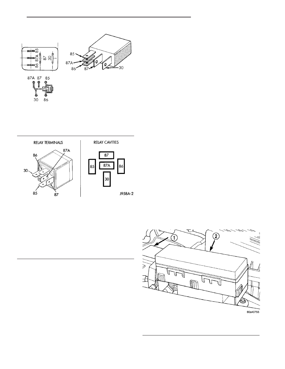
Fig. 2 ASD and Fuel Pump Relay Terminals—Type 1

30 - COMMON FEED
85 - COIL GROUND
86 - COIL BATTERY
87 - NORMALLY OPEN
87A - NORMALLY CLOSED

Fig. 3 ASD and Fuel Pump Relay Terminals—Type 2

30 - COMMON FEED
85 - COIL GROUND
86 - COIL BATTERY
87 - NORMALLY OPEN
87A - NORMALLY CLOSED

Fig. 4 Power Distribution Center (PDC)

1 - BATTERY
2 - POWER DISTRIBUTION CENTER (PDC)

TJ

IGNITION CONTROL

8I - 5

AUTO SHUT DOWN RELAY (Continued)

(3) Check condition of relay terminals and PDC

connector terminals for damage or corrosion. Repair
if necessary before installing relay.

(4) Check for pin height (pin height should be the

same for all terminals within the PDC connector).
Repair if necessary before installing relay.

INSTALLATION

The ASD relay is located in the Power Distribution

Center (PDC) (Fig. 4). Refer to label on PDC cover
for relay location.

(1) Install relay to PDC.
(2) Install cover to PDC.

CAMSHAFT POSITION
SENSOR - 2.4L

DESCRIPTION - 2.4L

The Camshaft Position Sensor (CMP) on the 2.4L

4–cylinder engine is bolted to the right-front side of
the cylinder head (Fig. 5).

OPERATION - 2.4L

The Camshaft Position Sensor (CMP) sensor con-

tains a hall effect device referred to as a sync signal
generator. A rotating target wheel (tonewheel) for the
CMP is located behind the exhaust valve-camshaft
drive gear (Fig. 6). The target wheel is equipped with
a cutout (notch) around 180 degrees of the wheel.
The CMP detects this cutout every 180 degrees of
camshaft gear rotation. Its signal is used in conjunc-

tion with the Crankshaft Position Sensor (CKP) to
differentiate between fuel injection and spark events.
It is also used to synchronize the fuel injectors with
their respective cylinders.

When the leading edge of the target wheel cutout

enters the tip of the CMP, the interruption of mag-
netic field causes the voltage to switch high, result-
ing in a sync signal of approximately 5 volts.

When the trailing edge of the target wheel cutout

leaves the tip of the CMP, the change of the magnetic
field causes the sync signal voltage to switch low to 0
volts.

REMOVAL - 2.4L

The Camshaft Position Sensor (CMP) on the 2.4L

4–cylinder engine is bolted to the right-front side of
the cylinder head (Fig. 7). Sensor position (depth) is
adjustable.

(1) Disconnect electrical connector at CMP sensor.
(2) Remove 2 sensor mounting bolts.
(3) Remove sensor from cylinder head by sliding

towards rear of engine.

INSTALLATION - 2.4L

The Camshaft Position Sensor (CMP) on the 2.4L

4–cylinder engine is bolted to the right-front side of
the cylinder head. Sensor position (depth) is
adjustable.

(1) Remove plastic, upper timing belt cover (timing

gear cover) (Fig. 8) by removing 3 bolts. Before
attempting to remove cover, remove electrical connec-

Fig. 5 CMP LOCATION - 2.4L

1 - CMP SENSOR
2 - ELECTRICAL CONNECTOR
3 - SLOTTED HOLES
4 - MOUNTING BOLTS (2)

Fig. 6 CMP FACE AT TARGET WHEEL-2.4L

1 - CAMSHAFT DRIVE GEAR
2 - TARGETWHEEL (TONEWHEEL)
3 - FACE OF CMP SENSOR
4 - CUTOUT (NOTCH)

8I - 6

IGNITION CONTROL

TJ

AUTO SHUT DOWN RELAY (Continued)

tor from Engine Coolant Temperature (ECT) sensor
(Fig. 8). This will prevent damage to sensor.

(2) Rotate (bump over) engine until camshaft tim-

ing gear and target wheel (tonewheel) are positioned
and aligned to face of sensor as shown in (Fig. 9). If
not positioned as shown in (Fig. 9), damage to
both sensor and target wheel will occur when
attempting to start engine. Face of sensor
MUST be behind target wheel while adjusting.

(3) Position sensor to cylinder head and install 2

sensor mounting bolts finger tight.

(4) SENSOR AIR GAP: .030” Set air gap between

rear of target wheel and face of sensor to .030”. This
can best be accomplished using an L-shaped, wire-
type spark plug gapping gauge (Fig. 10). A piece of
.030” brass shim stock may also be used.

(5) Gently push sensor forward until it contacts

gapping gauge. Do not push hard on sensor.
Tighten 2 sensor mounting bolts. Refer to torque
specifications.

CAUTION: After tightening sensor mounting bolts,
recheck air gap and adjust as necessary. Retorque
bolts.

(6) Install upper timing belt cover and 3 bolts.
(7) Connect electrical connector to ECT sensor.
(8) Connect electrical connector to CMP sensor.

Fig. 7 CMP LOCATION - 2.4L

1 - CMP SENSOR
2 - ELECTRICAL CONNECTOR
3 - SLOTTED HOLES
4 - MOUNTING BOLTS (2)

Fig. 8 UPPER TIMING BELT COVER/BOLTS-2.4L

1 - UPPER TIMING BELT COVER
2 - ELECTRICAL CONNECTOR (ECT)
3 - MOUNTING BOLTS (3)

Fig. 9 CMP FACE AT TARGET WHEEL-2.4L

1 - CAMSHAFT DRIVE GEAR
2 - TARGETWHEEL (TONEWHEEL)
3 - FACE OF CMP SENSOR
4 - CUTOUT (NOTCH)

TJ

IGNITION CONTROL

8I - 7

CAMSHAFT POSITION SENSOR - 2.4L (Continued)

CAMSHAFT POSITION
SENSOR - 4.0L

DESCRIPTION - 4.0L

The CMP (Camshaft Position Sensor) sensor (2)

(Fig. 11) is bolted to the side of the oil pump drive
assembly (5). The assembly is located on the right
side of the engine near the oil filter (Fig. 11).

OPERATION - 4.0L

The CMP sensor (1) (Fig. 12) uses a rotating hall

effect device called a target wheel (3) which is
attached to the oil pump drive shaft. The target
wheel contains sets of machined notches (2).

When the leading edge of a target wheel notch

passes by the tip of the CMP sensor, the interruption
of magnetic field causes the voltage to switch high
resulting in a sync signal of approximately 5 volts.

When the trailing edge of the target wheel notch

passes by the tip of the CMP sensor, the change of
the magnetic field causes the sync signal voltage to
switch low to 0 volts.

Fig. 10 CMP ADJUSTMENT - 2.4L

1 - FACE OF SENSOR
2 - WIRE GAPPING TOOL

Fig. 11 4.0L CMP LOCATION (’05)

1 - OIL PUMP DRIVE ASSEMBLY
2 - CMP
3 - CMP ELECTRICAL CONNECTOR
4 - HOUSING HOLD DOWN BOLT
5 - HOUSING
6 - PLASTIC COVER
7 - COVER SCREWS (2)

Fig. 12 4.0L CMP OPERATION

1 - CMP SENSOR
2 - TARGET WHEEL NOTCHES
3 - TARGET WHEEL

8I - 8

IGNITION CONTROL

TJ

CAMSHAFT POSITION SENSOR - 2.4L (Continued)


Content   ..  292  293  294  295   ..