Jeep Wrangler TJ. Manual - part 288


  Index      Jeep     Jeep Wrangler TJ - service repair manual 2005 year


Search            


Content   ..  286  287  288  289   ..


Jeep Wrangler TJ. Manual - part 288


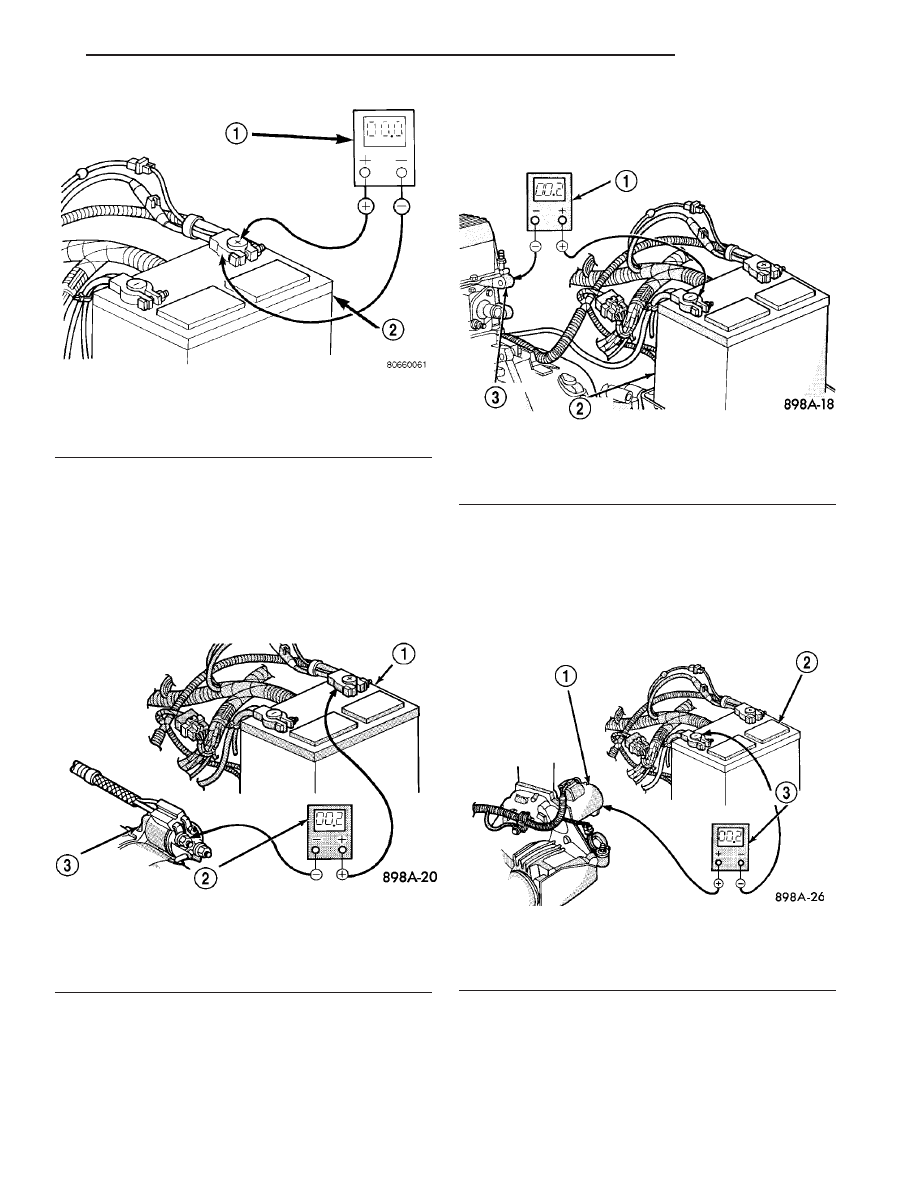
(3) Connect the voltmeter to measure between the

battery positive cable terminal clamp and the starter
solenoid B(+) terminal stud (Fig. 4). Rotate and hold
the ignition switch in the Start position. Observe the
voltmeter. If the reading is above 0.2 volt, clean and
tighten the battery positive cable eyelet terminal con-
nection at the starter solenoid B(+) terminal stud.
Repeat the test. If the reading is still above 0.2 volt,
replace the faulty battery positive cable.

(4) Connect the voltmeter to measure between the

battery negative cable terminal clamp and a good
clean ground on the engine block (Fig. 5). Rotate and
hold the ignition switch in the Start position.
Observe the voltmeter. If the reading is above 0.2
volt, clean and tighten the battery negative cable

eyelet terminal connection to the engine block.
Repeat the test. If the reading is still above 0.2 volt,
replace the faulty battery negative cable.

(5) Connect the positive lead of the voltmeter to

the starter housing. Connect the negative lead of the
voltmeter to the battery negative terminal post (Fig.
6). Rotate and hold the ignition switch in the Start
position. Observe the voltmeter. If the reading is
above 0.2 volt, correct the poor starter to engine
block ground contact.

If the resistance tests detect no feed circuit prob-

lems, refer to Starter Motor.

Fig. 3 Test Battery Positive Connection Resistance -

Typical

1 - VOLTMETER
2 - BATTERY

Fig. 4 Test Battery Positive Cable Resistance -

Typical

1 - BATTERY
2 - VOLTMETER
3 - STARTER MOTOR

Fig. 5 Test Ground Circuit Resistance - Typical

1 - VOLTMETER
2 - BATTERY
3 - ENGINE GROUND

Fig. 6 Test Starter Ground - Typical

1 - STARTER MOTOR
2 - BATTERY
3 - VOLTMETER

TJ

STARTING

8F - 35

STARTING (Continued)

CONTROL CIRCUIT TEST

The starter control circuit components should be

tested in the order in which they are listed, as fol-
lows:

Starter Relay

• Refer to Starter Relay.

Starter Solenoid

• Refer to Starter Motor.

Ignition Switch

• Refer to Ignition Switch and Key Lock Cyl-

inder for ignition switch diagnosis and testing proce-
dures.

Clutch Pedal Position Switch

• If the vehicle is equipped with a manual trans-

mission, refer to Clutch Pedal Position Switch for
clutch pedal position switch diagnosis and testing
procedures.

Park/Neutral Position Switch

• If the vehicle is equipped with an automatic

transmission,

refer

to

Park/Neutral

Position

Switch for park/neutral position switch diagnosis
and testing procedures.

INSPECTION - STARTING SYSTEM

The following starting system components should

be carefully inspected whenever any starting system
problem is encountered.

WARNING: ON VEHICLES EQUIPPED WITH AIR-
BAGS,

DISABLE

AIRBAG

SYSTEM

BEFORE

ATTEMPTING ANY STEERING WHEEL, STEERING
COLUMN, OR INSTRUMENT PANEL COMPONENT
DIAGNOSIS OR SERVICE. DISCONNECT AND ISO-
LATE

BATTERY

NEGATIVE

(GROUND)

CABLE,

THEN WAIT TWO MINUTES FOR AIRBAG SYSTEM
CAPACITOR TO DISCHARGE BEFORE PERFORM-
ING FURTHER DIAGNOSIS OR SERVICE. THIS IS
THE ONLY SURE WAY TO DISABLE AIRBAG SYS-
TEM. FAILURE TO TAKE PROPER PRECAUTIONS
COULD RESULT IN ACCIDENTAL AIRBAG DEPLOY-
MENT AND POSSIBLE PERSONAL INJURY.

Battery

• Visually inspect battery for indications of physi-

cal damage and loose or corroded cable connections.
Determine state-of-charge and cranking capacity of
battery. Charge or replace battery, if required. Refer
to Battery for battery cleaning and inspection proce-
dures.

Ignition Switch

• Visually inspect ignition switch for indications of

physical damage and loose or corroded wire harness
connections. Clean corroded connections as required.
Refer to Wiring Diagrams. Refer to Ignition
Switch and Key Lock Cylinder 
for ignition switch
service procedures.

Clutch Pedal Position Switch

• If vehicle is equipped with a manual transmis-

sion, visually inspect clutch pedal position switch for
indications of physical damage and loose or corroded
wire harness connections. Clean corroded connections
as required. Refer to Clutch Hydraulic Linkage for
clutch pedal position switch service procedures.

Park/Neutral Position Switch

• If vehicle is equipped with an automatic trans-

mission, visually inspect park/neutral position switch
for indications of physical damage and loose or cor-
roded wire harness connections. Clean corroded con-
nections

as

required.

Refer

to

Park/Neutral

Position Switch for park/neutral position switch
service procedures.

Starter Relay

• Visually inspect starter relay for indications of

physical damage and loose or corroded wire harness
connections. Clean corroded connections as required.
Refer to Starter Relay for starter relay service pro-
cedures.

Starter Motor

• Visually inspect starter motor for indications of

physical damage and loose or corroded wire harness
connections. Clean corroded connections as required.
If problem being diagnosed involves improper starter
engagement, disengagement or noise complaints,
starter motor should be removed. With starter motor
removed, inspect starter pinion and ring gears for
damaged or missing teeth. Replace faulty compo-
nents as required. Refer to Starter Motor for
removal/installation procedures.

Starter Solenoid

• Visually inspect starter solenoid for indications

of physical damage and loose or corroded wire har-
ness connections. Clean corroded connections as
required. Refer to Starter Motor for starter solenoid
service procedures.

Wiring

• Visually inspect starting system wire harnesses

for indications of physical damage. Repair or replace
any faulty wiring, as required. Refer to Wiring Dia-
grams 
for repair or connector and terminal service
procedures.

8F - 36

STARTING

TJ

STARTING (Continued)

SPECIFICATIONS

STARTER

Starter Motor and Solenoid

Manufacturer

Mitsubishi

Engine Application

2.4L, 4.0L

Power Rating

2.4L - 1.4 Kilowatt (1.9 Horsepower)
4.0L - 1.4 Kilowatt (1.9 Horsepower)

Voltage

12 Volts

** Number of Permanent Magnets

6

Number of Brushes

4

Drive Type

Planetary Gear Reduction

Free Running Test Voltage

11.2 Volts

Free Running Test Maximum Amperage Draw

90 Amperes

Free Running Test Minimum Speed

2.4L - 24400 rpm

4.0L - 2500 rpm

Solenoid Closing Maximum Voltage Required

7.8 Volts

*Cranking Amperage Draw Test

2.4L - 160 Amperes
4.0L - 160 Amperes

* Test at operating temperature. Cold engine, tight (new) engine, or heavy oil will increase starter amperage draw.

** The starter is equipped with permanent magnets. Never strike the starter case to attempt to loosen a sticking/
stuck armature as permanent magnets may crack or break.

TORQUE

DESCRIPTION

N-m

Ft. Lbs.

In. Lbs.

Starter Solenoid B+

Terminal Nut

11.3

-

100

Starter Mounting Bolts

(2.4L)

54

40

-

Starter Heat Shield

Mounting Bolts

6

-

55

Starter Mounting Bolt

(forward facing 4.0L)

41

30

-

Starter Mounting Bolt

(rearward facing 4.0L)

48

35

-

STARTER MOTOR

DIAGNOSIS AND TESTING - STARTER
MOTOR/SOLENOID

Correct starter motor operation can be confirmed

by performing the following free running bench test.
This test can only be performed with starter motor
removed from vehicle. Refer to starter motor specifi-
cations.

CAUTION: Permanent magnets are used in the
starter. Permanent magnet starters are highly sensi-
tive to hammering, shocks, external pressure and
reverse polarity. This starter motor must never be
clamped in a vise by starter field frame. The starter
should only be clamped by mounting flange. Do not
reverse battery cable connections to starter motor
when testing. The permanent magnets may be dam-
aged and starter rendered unserviceable if it is sub-
jected to any of these conditions.

TJ

STARTING

8F - 37

STARTING (Continued)

STARTER MOTOR TESTING

(1) Remove starter motor from vehicle. Refer to

Starter Motor Removal / Installation.

(2) Mount starter motor securely in a soft-jawed

bench vise. The vise jaws should be clamped on
mounting flange of starter motor. Never clamp on
starter motor by field frame.

(3) Connect a suitable volt-ampere tester and12-

volt battery to starter motor in series, and set amme-
ter to 100 ampere scale. See instructions provided by
manufacturer of volt-ampere tester being used.

(4) Install a jumper wire from solenoid terminal to

solenoid B(+) terminal stud. The starter motor should
operate. If starter motor fails to operate, replace
faulty starter motor.

(5) Adjust carbon pile load of tester to obtain free

running test voltage. Refer to starter motor free run-
ning test voltage specifications.

(6) Note reading on ammeter and compare reading

to free running test maximum amperage draw. Refer
to starter motor free running test maximum amper-
age draw specifications.

(7) If ammeter reading exceeds maximum amper-

age draw specification, replace faulty starter motor.

STARTER SOLENOID TESTING

This test can only be performed with starter motor

removed from vehicle.

(1) Remove starter motor from vehicle. Refer to

Starter Motor for removal/installation.

(2) Disconnect wire from solenoid field coil termi-

nal.

(3) Check for continuity between solenoid terminal

and solenoid field coil terminal with a continuity
tester (Fig. 7). There should be continuity. If OK, go
to Step 4. If not OK, replace faulty starter motor.

(4) Check for continuity between solenoid terminal

and solenoid case (Fig. 8). There should be continuity.
If not OK, replace faulty starter motor.

REMOVAL

2.4L

(1) Disconnect and isolate negative battery cable.
(2) Raise and support vehicle.
(3) While supporting starter motor, remove two

bolts securing starter motor to transmission (Fig. 9).

(4) Lower starter motor far enough to access and

remove nut securing battery cable to starter solenoid
B(+) terminal stud (Fig. 10). Always support starter
motor during this process. Do not let starter motor
hang from wire harness.

(5) Remove battery cable at starter.
(6) Disconnect solenoid terminal wire harness con-

nector from starter solenoid.

(7) Remove starter motor.

Fig. 7 CONTINUITY TEST BETWEEN SOLENOID

TERMINAL AND FIELD COIL TERMINAL

1 - SOLENOID
2 - SOLENOID TERMINAL
3 - OHMMETER
4 - FIELD COIL TERMINAL

Fig. 8 CONTINUITY TEST BETWEEN SOLENOID

TERMINAL AND SOLENOID CASE - TYPICAL

1 - SOLENOID
2 - SOLENOID TERMINAL
3 - OHMMETER

Fig. 9 STARTER - 2.4L

1 - STARTER
2 - MOUNTING BOLTS (2)

8F - 38

STARTING

TJ

STARTER MOTOR (Continued)


Content   ..  286  287  288  289   ..