Jeep Wrangler TJ. Manual - part 229


  Index      Jeep     Jeep Wrangler TJ - service repair manual 2005 year


Search            


Content   ..  227  228  229  230   ..


Jeep Wrangler TJ. Manual - part 229


(8) Thread Pilot Stud C-3288-B into rear cover bolt

hole below ring gear (Fig. 16).

(9) Attach Dial Indicator C-3339 to the pilot stud

and position indicator plunger on a flat surface of the
ring gear bolt head (Fig. 16).

(10) Push differential case to the pinion gear side

of the housing (Fig. 17) and zero dial indicator.

(11) Push differential case to the ring gear side

and record dial indicator reading (Fig. 18).

(12) Add the dial indicator reading to the starting

point shim thickness to determine total shim thick-
ness to achieve zero differential end play.

(13) Add 0.008 in. (0.2 mm) to the zero end play

total. This new total represents the thickness of
shims to compress or preload the new bearings when
the differential is installed.

(14) Rotate dial indicator out of the way.
(15) Remove differential case, dummy bearings

and starting point shims from the housing.

(16) Install pinion gear in the housing. Install the

yoke and establish the correct pinion rotating torque.

(17) Install differential case and dummy bearings

in the housing (without shims) and tighten retaining
cap bolts.

(18) Position the dial indicator plunger on a flat

surface between the ring gear bolt heads (Fig. 16).

(19) Push and hold differential case toward pinion

gear.

(20) Zero dial indicator face to pointer.
(21) Push and hold differential case to ring gear

side of the housing and record dial indicator reading.

(22) Subtract 0.002 in. (0.05 mm) from the dial

indicator reading to compensate for backlash between
ring and pinion gears. This total is the thickness of
shim required to achieve proper backlash.

(23) Subtract the backlash shim thickness from

the total preload shim thickness. The remainder is
the shim thickness required on the pinion side of the
housing.

(24) Rotate dial indicator out of the way on pilot

stud.

(25) Remove differential case and dummy bearings

from the housing.

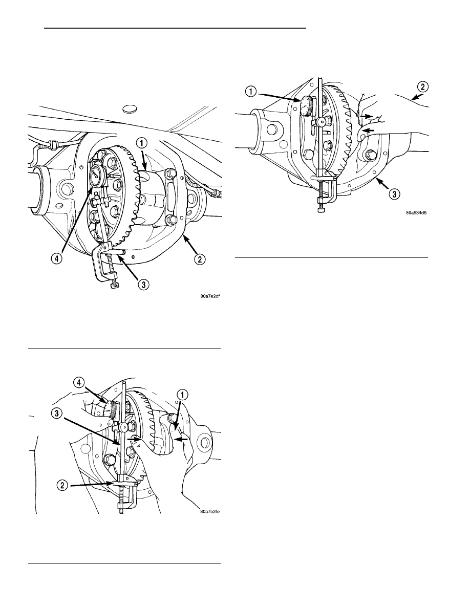
Fig. 16 DIFFERENTIAL SIDE PLAY MEASUREMENT

1 - DIFFERENTIAL CASE
2 - DIFFERENTIAL HOUSING
3 - PILOT STUD
4 - DIAL INDICATOR

Fig. 17 ZERO DIAL INDICATOR

1 - DIFFERENTIAL CASE TO PINION GEAR SIDE
2 - PILOT STUD
3 - DIAL INDICATOR EXTENSION
4 - ZERO DIAL INDICATOR FACE

Fig. 18 RECORD DIAL INDICATOR READING

1 - READ DIAL INDICATOR
2 - DIFFERENTIAL CASE TO RING GEAR SIDE
3 - DIFFERENTIAL HOUSING

TJ

REAR AXLE - 194RBI

3 - 93

REAR AXLE - 194RBI (Continued)

(26) Install new side bearing cones and cups on

differential case.

(27) Install spreader W-129-B and some compo-

nents of Adapter Set 6987 on differential housing and
spread axle opening enough to receive differential
case.

(28) Place side bearing shims into the housing

against the differential bearing bore.

(29) Install differential case in the housing.
(30) Rotate the differential case several times to

seat the side bearings.

(31) Position the indicator plunger against a ring

gear tooth (Fig. 19).

(32) Push and hold ring gear upward while not

allowing the pinion gear to rotate.

(33) Zero dial indicator face to pointer.
(34) Push and hold ring gear downward while not

allowing the pinion gear to rotate. Dial indicator
reading should be between 0.12 mm - 0.20 mm (0.005
in. - 0.008 in.). If backlash is not within specifications
transfer the necessary amount of shim thickness
from one side of the differential housing to the other
(Fig. 20).

(35) Verify differential case and ring gear runout

by measuring ring to pinion gear backlash at eight
locations around the ring gear. Readings should not
vary more than 0.05 mm (0.002 in.). If readings vary
more than specified, the ring gear or the differential
case is defective.

After the proper backlash is achieved, perform the

Gear Contact Pattern Analysis procedure.

GEAR CONTACT PATTERN

The ring gear and pinion teeth contact patterns

will show if the pinion depth is correct in the hous-
ing. It will also show if the ring gear backlash has
been adjusted correctly. The backlash can be adjusted

within specifications to achieve desired tooth contact
patterns.

The TOP LAND of the gear tooth is the top surface

of the tooth. The PROFILE of the gear tooth is the
depth of the tooth. The TOE of the gear is the por-
tion of the tooth surface at the end towards the cen-
ter. The HEEL of the gear is the portion of the tooth
at the outer-end. The ROOT of the gear tooth is the
lowest portion of the tooth (Fig. 21).

NOTE: If the PROFILE across the tooth is the same
it is a 3 Axis cut gear. If the PROFILE across the
tooth is tapered it is a 2 Axis cut gear.

Fig. 19 RING GEAR BACKLASH

1 - DIAL INDICATOR

Fig. 20 BACKLASH SHIM ADJUSTMENT

Fig. 21 GEAR DESCRIPTION

1 - TOP LAND
2 - PROFILE
3 - TOE
4 - HEEL
5 - ROOT

3 - 94

REAR AXLE - 194RBI

TJ

REAR AXLE - 194RBI (Continued)

(1) Apply a thin coat of hydrated ferric oxide or

equivalent to the drive and coast side of the ring gear
teeth.

(2) Wrap, twist, and hold a shop towel around the

pinion yoke to increase the turning resistance of the
pinion. This will provide a more distinct contact pat-
tern.

(3) With a boxed end wrench on a ring gear bolt,

rotate the differential case one complete revolution in
both directions while a load is being applied from
shop towel.

The areas on the ring gear teeth with the greatest

degree of contact against the pinion teeth will
squeeze the compound to the areas with the least
amount of contact. Note and compare patterns on the
ring gear teeth to Gear Tooth Contact Patterns
charts (Fig. 22) and (Fig. 23) and adjust pinion depth
and gear backlash as necessary.

DIFFERENTIAL BEARING PRELOAD CHECK

The final check on the differential assembly before

installing the axles is torque to rotate pinion and dif-
ferential combined. This will verify the correct differ-
ential bearing preload.

Torque to rotate the differential and pinion should

be the torque to rotate the pinion plus 0.79-1.24 N·m
(7-11 in. lbs.).

Fig. 22 PATTERN INTERPRETATION (GEAR CUT 2 AXIS)

TJ

REAR AXLE - 194RBI

3 - 95

REAR AXLE - 194RBI (Continued)

SPECIFICATIONS

REAR AXLE

AXLE SPECIFICATIONS

DESCRIPTION

SPECIFICATION

Axle Ratio

3.07, 3.73, 4.10, 4.56

Ring Gear Backlash

0.12-0.20 mm (0.005-0.008 in.)

Pinion Bearing Preload - Original Bearings

1-2 N·m (10-20 in. lbs.)

Pinion Bearing Preload - New Bearings

2-4 N·m (20-35 in. lbs.)

TORQUE SPECIFICATIONS

DESCRIPTION

N·m

Ft. Lbs.

In. Lbs.

Differential Cover Bolts

41

30

-

Bearing Cap Bolts

77

57

-

Ring Gear Bolts

136

100

-

Pinion Nut Min / Max

271-475

200-350

-

Pinion Mate Shaft Screw

16.25

12

-

Fig. 23 PATTERN INTERPRETATION (GEAR CUT 3 AXIS)

3 - 96

REAR AXLE - 194RBI

TJ

REAR AXLE - 194RBI (Continued)


Content   ..  227  228  229  230   ..