Jeep Wrangler TJ. Manual - part 216


  Index      Jeep     Jeep Wrangler TJ - service repair manual 2005 year


Search            


Content   ..  214  215  216  217   ..


Jeep Wrangler TJ. Manual - part 216


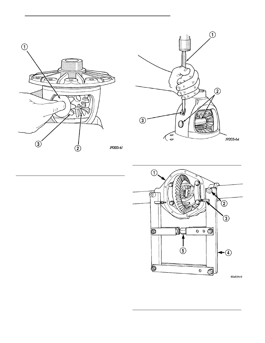
(4) Rotate differential side gears and remove pin-

ion mate gears and thrust washers (Fig. 54).

(5) Remove differential side gears and thrust

washers.

ASSEMBLY

(1) Install differential side gears and thrust wash-

ers.

(2) Install pinion mate gears and thrust washers.
(3) Install pinion gear mate shaft. Align roll pin

holes in shaft and the differential case.

(4) Install pinion mate shaft roll pin in the differ-

ential case (Fig. 55).

(5) Install the ring gear.

INSTALLATION

NOTE: If replacement differential bearings or differ-
ential case are being installed, differential side
bearing shim requirements may change. Refer to
Adjustments (Differential Bearing Preload and Gear
Backlash) to determine the proper shim selection.

(1) Position Spreader W-129-B and Adapter Kit

6987, with the tool dowel pins seated in the locating
holes (Fig. 56). Install holddown clamps and tighten
turnbuckle finger-tight.

Fig. 54 PINION MATE GEAR

1 - THRUST WASHER
2 - SIDE GEAR
3 - PINION MATE GEAR

Fig. 55 MATE SHAFT ROLL PIN

1 - PUNCH
2 - PINION MATE SHAFT
3 - MATE SHAFT LOCKPIN

Fig. 56 SPREADER LOCATION

1 - AXLE HOUSING
2 - DOWEL
3 - SAFETY HOLD DOWN
4 - SPREADER
5 - TURNBUCKLE

TJ

FRONT AXLE - 181FBI

3 - 41

DIFFERENTIAL (Continued)

(2) Install a Pilot Stud C-3288-B at the left side of

the differential housing. Attach Dial Indicator C-3339
to pilot stud. Load the lever adapter against the
opposite side of the housing (Fig. 57) and zero indi-
cator.

(3) Spread housing while measuring the distance

with the dial indicator (Fig. 58).

CAUTION: Do not spread over 0.50 mm (0.020 in).
Failure to heed caution may result in damage.

(4) Remove dial indicator.
(5) Install differential case in the housing. Tap dif-

ferential case to seat bearings cups in the housing.

(6) Install bearing caps at their original locations

(Fig. 59).

(7) Loosely install differential bearing cap bolts.
(8) Remove axle housing spreader.
(9) Tighten bearing cap bolts to 61 N·m (45 ft.

lbs.).

(10) Install hub bearings and axle shafts.
(11) Install differential cover.

Fig. 57 DIAL INDICATOR LOCATION

1 - CLAMP
2 - DIAL INDICATOR
3 - LEVER ADAPTER
4 - SPREADER
5 - PILOT STUD

Fig. 58 SPREAD DIFFERENTIAL HOUSING

1 - INDICATOR
2 - SPREADER

Fig. 59 BEARING CAP IDENTIFICATION

1 - INSTALLATION REFERENCE LETTERS
2 - INSTALLATION REFERENCE LETTERS

3 - 42

FRONT AXLE - 181FBI

TJ

DIFFERENTIAL (Continued)

DIFFERENTIAL CASE
BEARINGS

REMOVAL

(1) Remove bearings from the differential case

with Puller/Press C-293-PA, C-293-39 Adapter and
Plug SP-3289 (Fig. 60).

INSTALLATION

NOTE: If replacement differential side bearings or
differential case are being installed, differential side
bearing shim requirements may change. Refer to
Adjustments (Differential Bearing Preload and Gear
Backlash) to determine the proper shim selection.

(1) Install differential side bearing shims onto dif-

ferential case hubs.

(2) Install differential side bearings with Installer

C-3716-A and Handle C-4171 (Fig. 61).

Fig. 60 DIFFERENTIAL BEARING

1 - ADAPTERS
2 - BEARING
3 - DIFFERENTIAL
4 - PLUG
5 - PULLER

Fig. 61 DIFFERENTIAL CASE BEARING

1 - INSTALLER
2 - HANDLE

TJ

FRONT AXLE - 181FBI

3 - 43

PINION GEAR/RING GEAR

REMOVAL

NOTE: The ring and pinion gears are serviced as a
matched set. Never replace one gear without replac-
ing the other matched gear.

(1) Remove differential from axle housing.
(2) Secure differential case in a vise with soft

metal jaw (Fig. 62).

(3) Remove ring gear bolts from the differential

case.

(4) Drive ring gear off the differential case with a

dead-blow hammer (Fig. 62).

(5) Hold yoke with Spanner Wrench 6958 and

remove the pinion nut and washer (Fig. 63).

(6) Remove pinion yoke with Remover C-452 and

Flange Wrench C-3281 (Fig. 64).

Fig. 62 RING GEAR

1 - DIFFERENTAIL CASE
2 - RING GEAR
3 - HAMMER

Fig. 63 YOKE SPANNER WRENCH

1 - PINION YOKE
2 - SPANNER WRENCH
3 - PIPE

Fig. 64 PINION YOKE

1 - FLANGE WRENCH
2 - PINION YOKE
3 - REMOVER

3 - 44

FRONT AXLE - 181FBI

TJ


Content   ..  214  215  216  217   ..