Jeep Liberty KJ. Manual - part 976


  Index      Jeep     Jeep Liberty KJ - service repair manual 2006 year


Search            


Content   ..  974  975  976  977   ..


Jeep Liberty KJ. Manual - part 976


CONDITION

POSSIBLE CAUSE

CORRECTION

EXCESSIVE PLAY IN STEERING
WHEEL

1. Worn or loose suspension or
steering components.

1. Inspect and repair as necessary.

2. Worn or loose wheel bearings.

2. Inspect and replace bearings.

3. Steering gear mounting.

3. Tighten / replace gear mounting
bolts/ isolators to specification.

4. Gear out of adjustment.

4. Replace gear.

5. Worn or loose steering
intermediate shaft.

5. Inspect and replace as
necessary.

VEHICLE PULLS, DRIFTS OR
LEADS TO ONE SIDE.

1. Tire Pressure.

1. Adjust tire pressure.

2. Radial tire lead.

2. Rotate tires.

3. Brakes dragging.

3. Repair as necessary.

4. Wheel alignment.

4. Align front end.

POWER STEERING FLOW AND PRESSURE

The following procedure is used to test the operation
of the power steering system on the vehicle. This test
will provide the gallons per minute (GPM) or flow rate
of the power steering pump along with the maximum
relief pressure. Perform test any time a power steering
system problem is present. This test will determine if
the power steering pump or power steering gear is not
functioning properly. The following pressure and flow
test is performed using Power Steering Analyzer Tool
kit 6815 and Adapter Kit 6893.

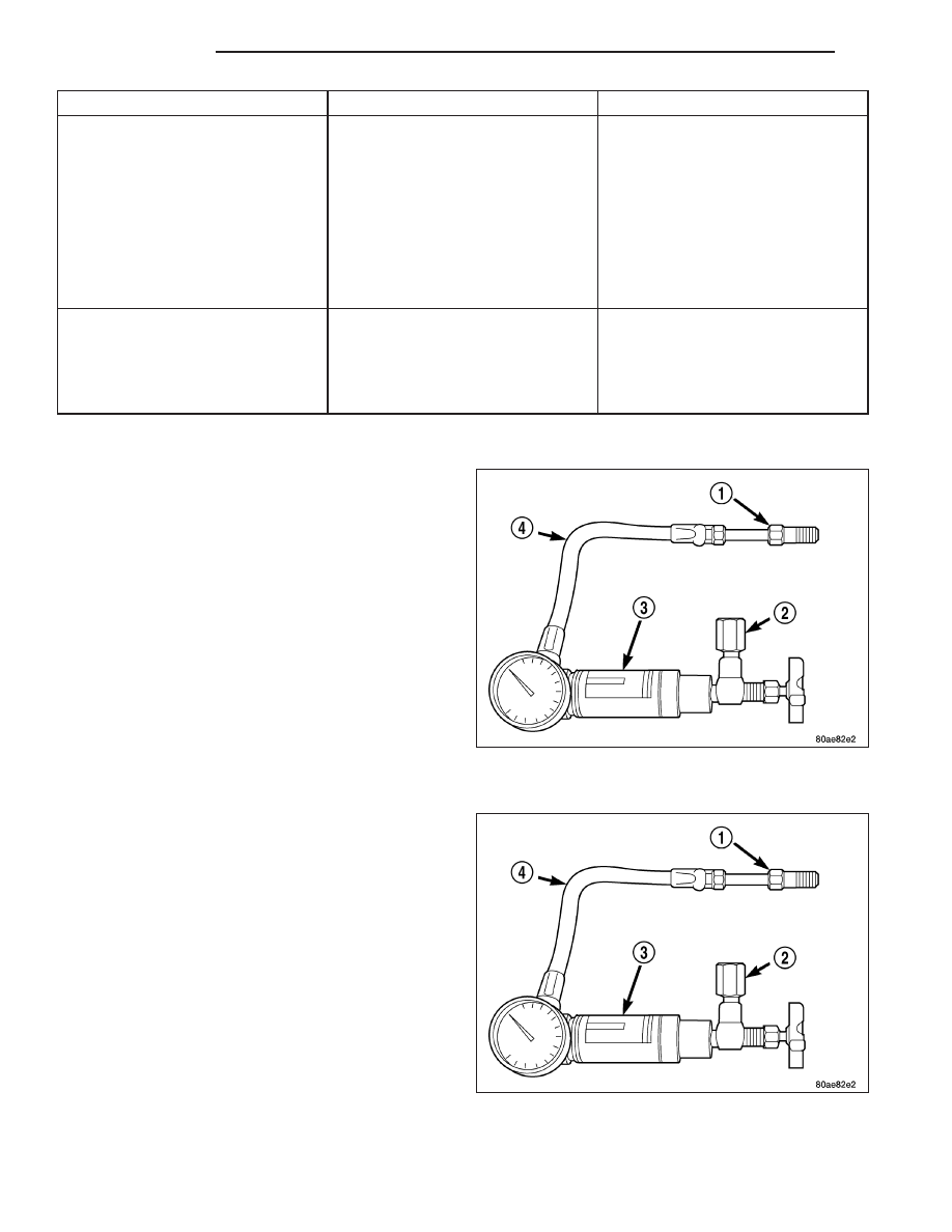
FLOW AND PRESSURE TEST

1. Check the power steering belt to ensure it is in

good condition and adjusted properly.

2. Connect pressure gauge hose from the Power

Steering Analyzer to Tube 6844.

3. Connect Adapter 6826 to Power Steering Analyzer

test valve end.

4. Disconnect the high pressure hose from the power

steering pump.

5. Connect the tube to the pump hose fitting.

6. Connect the power steering hose from the steering

gear to the adapter.

7. Open the test valve completely.

8. Start engine and let idle long enough to circulate power steering fluid through flow/pressure test gauge and to get

air out of the fluid. Then shut off engine.

9. Check fluid level, add fluid as necessary. Start engine again and let idle.

10. Check for air bubbles, Evacuate if necessary.

19 - 4

STEERING

KJ

11. Gauge should read below 862 kPa (125 psi). If above, inspect the hoses for restrictions and repair as neces-

sary. The initial pressure reading should be in the range of 345-552 kPa (50-80 psi).

12. Increase the engine speed to 1500 RPM and read the flow meter. If the flow rate (GPM) is below specification,

(refer to pump specification chart for GPM) the pump should be replaced.

CAUTION: The following test procedure involves testing maximum pump pressure output and flow control
valve operation. Do not leave valve closed for more than three seconds as the pump could be damaged.

13. Close valve fully three times and record highest pressure indicated each time. All three readings must be

above specifications and within 345 kPa (50 psi) of each other.

Pressures above specifications but not within 345 kPa (50 psi) of each other, replace pump.

Pressures within 345 kPa (50 psi) of each other but below specifications, replace pump.

14. Open the test valve and turn the steering wheel to the extreme left and right positions three times against the

stops. Record the highest pressure reading at each position. Compare readings to the pump specifications
chart. If pressures readings are not within 50 psi of each other, the gear is leaking internally and must be
replaced.

CAUTION: Do not force the pump to operate against the stops for more than 2 to 3 seconds at a time
because, pump damage will result.

PUMP SPECIFICATION

ENGINE

RELIEF PRESSURE

FLOW RATE (GPM) AT 1500 RPM

ALL

10342 kPa, PREFERRED (1450 psi) with a MAX

1550 psi & 7929 kPa, MIN (1400 psi)

2.4 - 2.8

KJ

STEERING

19 - 5

COLUMN

TABLE OF CONTENTS

page

page

COLUMN

DESCRIPTION . . . . . . . . . . . . . . . . . . . . . . . . . . . . . . . . . 7
OPERATION - SERVICE PRECAUTIONS . . . . . . . . . 7
REMOVAL . . . . . . . . . . . . . . . . . . . . . . . . . . . . . . . . . . . . . 7
INSTALLATION . . . . . . . . . . . . . . . . . . . . . . . . . . . . . . . . 9
SPECIFICATIONS

TORQUE CHART . . . . . . . . . . . . . . . . . . . . . . . . . . . 11

SPECIAL TOOLS

STEERING COLUMN . . . . . . . . . . . . . . . . . . . . . . . . 13

IGNITION SWITCH

DESCRIPTION . . . . . . . . . . . . . . . . . . . . . . . . . . . . . . . . 14
DIAGNOSIS AND TESTING - IGNITION

SWITCH . . . . . . . . . . . . . . . . . . . . . . . . . . . . . . . . . . . . 14

REMOVAL . . . . . . . . . . . . . . . . . . . . . . . . . . . . . . . . . . . . 14

INSTALLATION . . . . . . . . . . . . . . . . . . . . . . . . . . . . . . . 15

KEY-IN IGNITION SWITCH

DESCRIPTION . . . . . . . . . . . . . . . . . . . . . . . . . . . . . . . . 16
DIAGNOSIS AND TESTING - KEY-IN IGNITION

SWITCH . . . . . . . . . . . . . . . . . . . . . . . . . . . . . . . . . . . . 16

KEY CYLINDER

REMOVAL . . . . . . . . . . . . . . . . . . . . . . . . . . . . . . . . . . . . 17
INSTALLATION . . . . . . . . . . . . . . . . . . . . . . . . . . . . . . . 17

INTERMEDIATE SHAFT

REMOVAL . . . . . . . . . . . . . . . . . . . . . . . . . . . . . . . . . . . . 18
INSTALLATION . . . . . . . . . . . . . . . . . . . . . . . . . . . . . . . 19

STEERING WHEEL

REMOVAL . . . . . . . . . . . . . . . . . . . . . . . . . . . . . . . . . . . . 20
INSTALLATION . . . . . . . . . . . . . . . . . . . . . . . . . . . . . . . 20

19 - 6

COLUMN

KJ

COLUMN

DESCRIPTION

NOTE: The steering column on vehicles with an automatic transmission may not be equipped with an inter-
nal locking shaft that allows the ignition key cylinder to be locked with the key. Alternative methods of lock-
ing the steering wheel for service will have to be used.

The standard non-tilt and tilt steering column has been designed to be serviced as an assembly. The column is
connected to the steering gear with a one piece shaft. The upper half has a support bearing mounted to a bracket.
The bracket mounts to the frame rail with two nuts. The shaft is serviceable. The key cylinder, switches, clock
spring, trim shrouds and steering wheel are serviced separately.

OPERATION - SERVICE PRECAUTIONS

Safety goggles should be worn at all times when working on steering columns.

To service the steering wheel, switches or airbag, refer to Electrical - Restraints and follow all WARNINGS and
CAUTIONS.

WARNING: The airbag system is a sensitive, complex electro-mechanical unit. Before attempting to diag-
nose, remove or install the airbag system components you must first disconnect and isolate the battery
negative (ground) cable. Then wait two minutes for the system capacitor to discharge. Failure to do so
could result in accidental deployment of the airbag and possible personal injury. The fasteners, screws, and
bolts, originally used for the airbag components, have special coatings and are specifically designed for the
airbag system. They must never be replaced with any substitutes. Anytime a new fastener is needed,
replace with the correct fasteners provided in the service package or fasteners listed in the parts books.

REMOVAL

1. Position front wheels straight ahead.

2. Remove and isolate the negative ground cable from the battery.

3. Remove the airbag, (Refer to 8 - ELECTRICAL/RESTRAINTS/DRIVER AIRBAG - REMOVAL).

NOTE: If equipped with cruise control, disconnect clock spring harness from the cruise switch harness on
the steering wheel.

4. Remove

the

steering

wheel

(2)

with

puller

C-3894–A (1) or an appropriate puller (Refer to 19
-

STEERING/COLUMN/STEERING

WHEEL

-

REMOVAL).

KJ

COLUMN

19 - 7


Content   ..  974  975  976  977   ..