Jeep Liberty KJ. Manual - part 970


  Index      Jeep     Jeep Liberty KJ - service repair manual 2006 year


Search            


Content   ..  968  969  970  971   ..


Jeep Liberty KJ. Manual - part 970


BOOST PRESSURE SENSOR
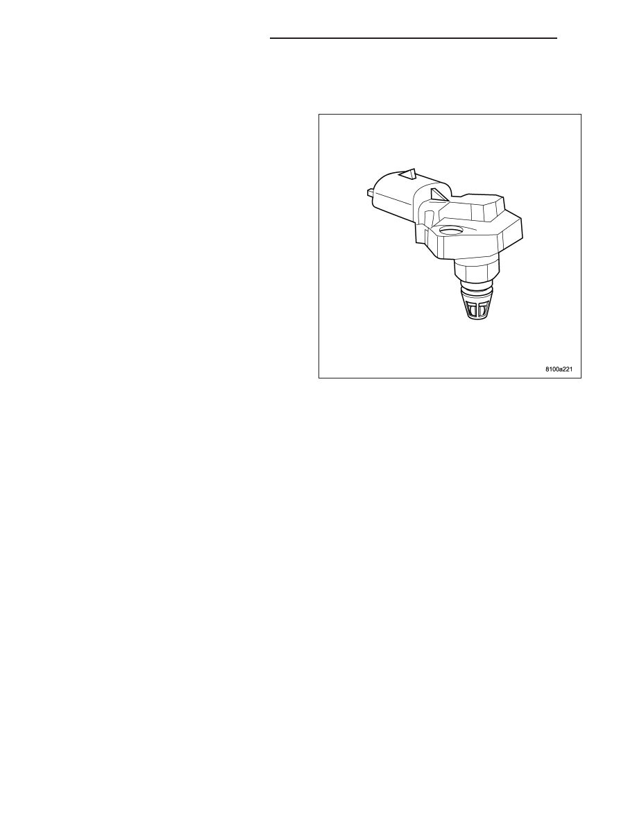
DESCRIPTION

The boost pressure/intake air temperature sensor is
mounted to the top of the intake manifold. The sensor
allows the ECM to monitor air pressure within the
intake manifold. This sensor is also used to monitor
the intake air temperature.

OPERATION

When the intake manifold pressure is low sensor voltage output is 0.25-1.8 volts at the ECM. When the intake
manifold pressure is high due to turbo boost, sensor voltage output is 2.0-4.7 volts. The sensor receives a 5-volts
reference from the ECM. Sensor ground is also provides by the ECM. The ECM uses boost pressure combined with
intake air temerature to determine the volume of air entering the engine.

DIAGNOSIS AND TESTING - BOOST PRESSURE/INTAKE AIR TEMPERATURE
SENSOR

If the boost pressure sensor fails, the ECM records a DTC into memory and continues to operate the engine in one
of the three limp-in modes. When the ECM is operating in this mode, a loss of power will be present, as if the
turbocharger was not operating. The best method for diagnosing faults with the boost pressure sensor is with the
scan tool. Refer to the Diesel Powertrain Diagnostic Manual for more information.

14 - 100

FUEL INJECTION - 2.8L DIESEL

KJ

REMOVAL

1. Disconnect negative battery cable.

2. Remove engine cover and bracket assembly (Refer

to 9 - ENGINE COVER - REMOVAL).

3. Disconnect sensor electrical connector.

4. Remove retaining bolts and remove sensor (1)

from cylinder head cover/intake manifold.

INSTALLATION

1. Install sensor (1) and retaining bolts into cylinder

head cover/intake manifold. Torque to 5.4 N·m (48
in. lbs.)..

2. Connect sensor electrical connector.

3. Install engine cover and bracket assembly (Refer to

9 - ENGINE - INSTALLATION).

4. Connect negative battery cable.

KJ

FUEL INJECTION - 2.8L DIESEL

14 - 101

CAMSHAFT POSITION SENSOR

DESCRIPTION

The camshaft position sensor (2) is mounted on the
cylinder head cover toward the rear of the engine. The
camshaft sensor utilizes a non contact method on one
segment of the camshaft to record the camshaft posi-
tion. When the ECM receives the signal from this sen-
sor, it can then detect TDC of cylinder number one.
The signal from the camshaft sensor is only required
during engine starting. Injection timing is synchronized
by means of the camshaft signal and the crankshaft
signal.

OPERATION

On the camshaft sensor’s signal line, a high signal corresponds to a voltage of 0-5V. If the segment machined into
the exhaust camshaft sprocket is positioned opposite the camshaft sensor, the camshaft signal is low, approximately
0V. This signal is used by the engine control module (ECM) for detecting ignition TDC of cylinder 1 as the engine
rotates. If no signal is supplied by the camshaft position sensor, the vehicle will not start because cylinder order can
not be detected. If the signal is lost while the engine is running the vehicle will continue to run until shut off.

REMOVAL

1. Disconnect negative battery cable.

2. Remove engine cover

3. Disconnect camshaft position sensor (1) electrical

connector.

4. Remove retaining bolt, seal and remove sensor.

14 - 102

FUEL INJECTION - 2.8L DIESEL

KJ

INSTALLATION

1. Install camshaft position sensor (1) and tighten bolt

to 10.8 N·m (95 in lbs.).

2. Reconnect electrical connector.

3. Install engine cover.

4. Reconnect negative battery cable.

KJ

FUEL INJECTION - 2.8L DIESEL

14 - 103


Content   ..  968  969  970  971   ..