Jeep Liberty KJ. Manual - part 969


  Index      Jeep     Jeep Liberty KJ - service repair manual 2006 year


Search            


Content   ..  967  968  969  970   ..


Jeep Liberty KJ. Manual - part 969


SENSOR-THROTTLE POSITION

DESCRIPTION

The 3-wire Throttle Position Sensor (TPS) is mounted on the throttle body and is connected to the throttle blade
shaft.

OPERATION

The 3-wire TPS provides the Powertrain Control Module (PCM) with an input signal (voltage) that represents the
throttle blade position of the throttle body. The sensor is connected to the throttle blade shaft. As the position of the
throttle blade changes, the output voltage of the TPS changes.

The PCM supplies approximately 5 volts to the TPS. The TPS output voltage (input signal to the PCM) represents
the throttle blade position. The PCM receives an input signal voltage from the TPS. This will vary in an approximate
range of from 0.26 volts at minimum throttle opening (idle), to 4.49 volts at wide open throttle. Along with inputs from
other sensors, the PCM uses the TPS input to determine current engine operating conditions. In response to engine
operating conditions, the PCM will adjust fuel injector pulse width and ignition timing.

The PCM needs to identify the actions and position of the throttle blade at all times. This information is needed to
assist in performing the following calculations:

Ignition timing advance

Fuel injection pulse-width

Idle (learned value or minimum TPS)

Off-idle (0.06 volt)

Wide Open Throttle (WOT) open loop (2.608 volts above learned idle voltage)

Deceleration fuel lean out

Fuel cutoff during cranking at WOT (2.608 volts above learned idle voltage)

A/C WOT cutoff (certain automatic transmissions only)
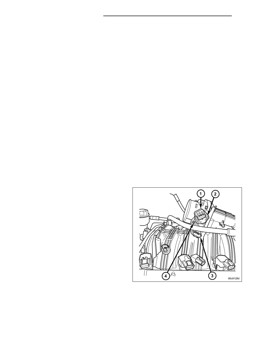
REMOVAL

The Throttle Position Sensor (TPS) (1) is mounted to
the throttle body.

1. Disconnect TPS electrical connector.

2. Remove two TPS mounting screws (2).

3. Remove TPS.

14 - 96

FUEL INJECTION - 3.7L GAS

KJ

INSTALLATION

The throttle shaft end of the throttle body (3) slides
into a socket (4) in the TPS. The TPS must be
installed so that it can be rotated a few degrees. (If
sensor will not rotate, install sensor with throttle shaft
on other side of socket tangs). The TPS will be under
slight tension when rotated.

1. Install TPS and retaining screws.

2. Tighten screws to 7 N·m (60 in. lbs.) torque.

3. Connect TPS electrical connector to TPS.

4. Manually operate throttle (by hand) to check for

any TPS binding before starting engine.

5. Install air cleaner tube to throttle body.

KJ

FUEL INJECTION - 3.7L GAS

14 - 97

FUEL INJECTION - 2.8L DIESEL

TABLE OF CONTENTS

page

page

ACCELERATOR PEDAL POSITION SENSOR

DESCRIPTION . . . . . . . . . . . . . . . . . . . . . . . . . . . . . . . . 99
REMOVAL . . . . . . . . . . . . . . . . . . . . . . . . . . . . . . . . . . . . 99
INSTALLATION . . . . . . . . . . . . . . . . . . . . . . . . . . . . . . . 99

BOOST PRESSURE SENSOR

DESCRIPTION . . . . . . . . . . . . . . . . . . . . . . . . . . . . . . . 100
OPERATION . . . . . . . . . . . . . . . . . . . . . . . . . . . . . . . . . 100
DIAGNOSIS AND TESTING - BOOST

PRESSURE/INTAKE AIR TEMPERATURE
SENSOR . . . . . . . . . . . . . . . . . . . . . . . . . . . . . . . . . . 100

REMOVAL . . . . . . . . . . . . . . . . . . . . . . . . . . . . . . . . . . . 101
INSTALLATION . . . . . . . . . . . . . . . . . . . . . . . . . . . . . . 101

CAMSHAFT POSITION SENSOR

DESCRIPTION . . . . . . . . . . . . . . . . . . . . . . . . . . . . . . . 102
OPERATION . . . . . . . . . . . . . . . . . . . . . . . . . . . . . . . . . 102
REMOVAL . . . . . . . . . . . . . . . . . . . . . . . . . . . . . . . . . . . 102
INSTALLATION . . . . . . . . . . . . . . . . . . . . . . . . . . . . . . 103

CRANKSHAFT POSITION SENSOR

DESCRIPTION . . . . . . . . . . . . . . . . . . . . . . . . . . . . . . . 104
OPERATION . . . . . . . . . . . . . . . . . . . . . . . . . . . . . . . . . 104
REMOVAL . . . . . . . . . . . . . . . . . . . . . . . . . . . . . . . . . . . 104
INSTALLATION . . . . . . . . . . . . . . . . . . . . . . . . . . . . . . 105

FUEL INJECTOR

DESCRIPTION

FUEL INJECTOR . . . . . . . . . . . . . . . . . . . . . . . . . . . 106

OPERATION . . . . . . . . . . . . . . . . . . . . . . . . . . . . . . . . . 107
STANDARD PROCEDURE

CLEANING FUEL INJECTORS . . . . . . . . . . . . . . 108

INJECTOR CLASSIFICATION . . . . . . . . . . . . . . . 109

REMOVAL . . . . . . . . . . . . . . . . . . . . . . . . . . . . . . . . . . . 110
INSTALLATION . . . . . . . . . . . . . . . . . . . . . . . . . . . . . . . 111

FUEL PRESSURE SENSOR

DESCRIPTION . . . . . . . . . . . . . . . . . . . . . . . . . . . . . . . 112
OPERATION . . . . . . . . . . . . . . . . . . . . . . . . . . . . . . . . . 112
REMOVAL . . . . . . . . . . . . . . . . . . . . . . . . . . . . . . . . . . . 112
INSTALLATION . . . . . . . . . . . . . . . . . . . . . . . . . . . . . . 113

FUEL PRESSURE SOLENOID

DESCRIPTION . . . . . . . . . . . . . . . . . . . . . . . . . . . . . . . 114
OPERATION . . . . . . . . . . . . . . . . . . . . . . . . . . . . . . . . . 114
REMOVAL . . . . . . . . . . . . . . . . . . . . . . . . . . . . . . . . . . . 115
INSTALLATION . . . . . . . . . . . . . . . . . . . . . . . . . . . . . . 115

FUEL TEMPERATURE SENSOR

DESCRIPTION . . . . . . . . . . . . . . . . . . . . . . . . . . . . . . . 116
OPERATION . . . . . . . . . . . . . . . . . . . . . . . . . . . . . . . . . 116
REMOVAL . . . . . . . . . . . . . . . . . . . . . . . . . . . . . . . . . . . 116
INSTALLATION . . . . . . . . . . . . . . . . . . . . . . . . . . . . . . 117

INTAKE AIR TEMPERATURE SENSOR

DESCRIPTION . . . . . . . . . . . . . . . . . . . . . . . . . . . . . . . 118
OPERATION . . . . . . . . . . . . . . . . . . . . . . . . . . . . . . . . . 118
REMOVAL . . . . . . . . . . . . . . . . . . . . . . . . . . . . . . . . . . . 118
INSTALLATION . . . . . . . . . . . . . . . . . . . . . . . . . . . . . . 118

MASS AIR FLOW SENSOR

DESCRIPTION . . . . . . . . . . . . . . . . . . . . . . . . . . . . . . . 119
OPERATION . . . . . . . . . . . . . . . . . . . . . . . . . . . . . . . . . 119
REMOVAL . . . . . . . . . . . . . . . . . . . . . . . . . . . . . . . . . . . 119
INSTALLATION . . . . . . . . . . . . . . . . . . . . . . . . . . . . . . 119

14 - 98

FUEL INJECTION - 2.8L DIESEL

KJ

ACCELERATOR PEDAL POSITION SENSOR

DESCRIPTION

The Accelerator Pedal Position (APP) Sensor is a Hall Effect, angle of rotation sensor. The Accelerator Pedal Posi-
tion sensor is located inside the accelerator pedal assembly. A magnet located in the pedal shaft cylinder rotates
around a hall effect pick-up. The voltage signal increases as the accelerator pedal depresses. The APP sensor
receives a 5–volt reference signal from the ECM and based upon the position of the pedal shift magnet relative to
the windows on the Hall effect sensor, a portion of the 5 volts is returned to the ECM indicating pedal position.

REMOVAL

1. Disconnect negative battery cable.

2. Disconnect accelerator pedal position sensor elec-

trical connector.

3. Remove accelerator pedal position sensor assem-

bly mounting bolts.

4. Open accelerator pedal position sensor assembly

and disconnect accelerator cable.

5. Remove

accelerator

pedal

position

sensor

assembly.

INSTALLATION

Position the APP sensor and install the fasteners hand
tight.

1. Tighten the APP sensor fasteners to 10.8N·m (96

in. lbs.).

2. Connect the APP sensor wiring harness connector.

3. Connect negative battery cable.

KJ

FUEL INJECTION - 2.8L DIESEL

14 - 99


Content   ..  967  968  969  970   ..