Jeep Liberty KJ. Manual - part 965
RELAY-FUEL PUMP
DESCRIPTION
The 5-pin, 12-volt, fuel pump relay is located in the Power Distribution Center (PDC). Refer to the label on the PDC
cover for relay location.
OPERATION
The Powertrain Control Module (PCM) energizes the electric fuel pump through the fuel pump relay. The fuel pump
relay is energized by first applying battery voltage to it when the ignition key is turned ON, and then applying a
ground signal to the relay from the PCM.
Whenever the ignition key is turned ON, the electric fuel pump will operate. But, the PCM will shut-down the ground
circuit to the fuel pump relay in approximately 1–3 seconds unless the engine is operating or the starter motor is
engaged.
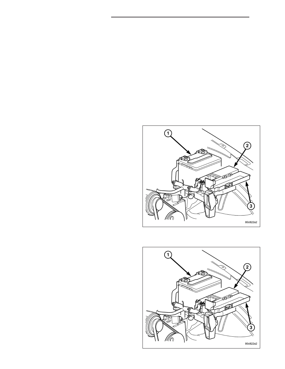
REMOVAL
The fuel pump relay is located in the Power Distribu-
tion Center (PDC) (2). Refer to label on PDC cover (3)
for relay location.
1. Remove PDC cover (3).
2. Remove relay from PDC.
3. Check condition of relay terminals and PDC con-
nector terminals for damage or corrosion. Repair if
necessary before installing relay.
4. Check for pin height (pin height should be the
same for all terminals within the PDC connector).
Repair if necessary before installing relay.
INSTALLATION
The fuel pump relay is located in the Power Distribu-
tion Center (PDC) (2). Refer to label on PDC cover (3)
for relay location.
1. Install relay to PDC.
2. Install cover (3) to PDC.
14 - 80
FUEL INJECTION - 3.7L GAS
KJ