Jeep Liberty KJ. Manual - part 908


  Index      Jeep     Jeep Liberty KJ - service repair manual 2006 year


Search            


Content   ..  906  907  908  909   ..


Jeep Liberty KJ. Manual - part 908


53. Lower vehicle.

54. Remove left side engine mount retaining nut.

55. Remove exhaust manifold rear heat shield.

56. Disconnect the fuel supply and return lines.

57. Remove crankshaft sensor heat shield.

58. Disconnect crankshaft position sensor, located on the right rear of the engine.

59. Remove the oil separator from the cylinder head cover/intake manifold.

60. Disconnect oil pressure sensor. Make certain everything is disconnected from the engine assembly.

61. Place a floor jack under the transmission to support the transmission.

62. With engine and transmission supported by a lifting device separate the engine from the transmission.

63. Lift the engine assembly out of the engine bay.
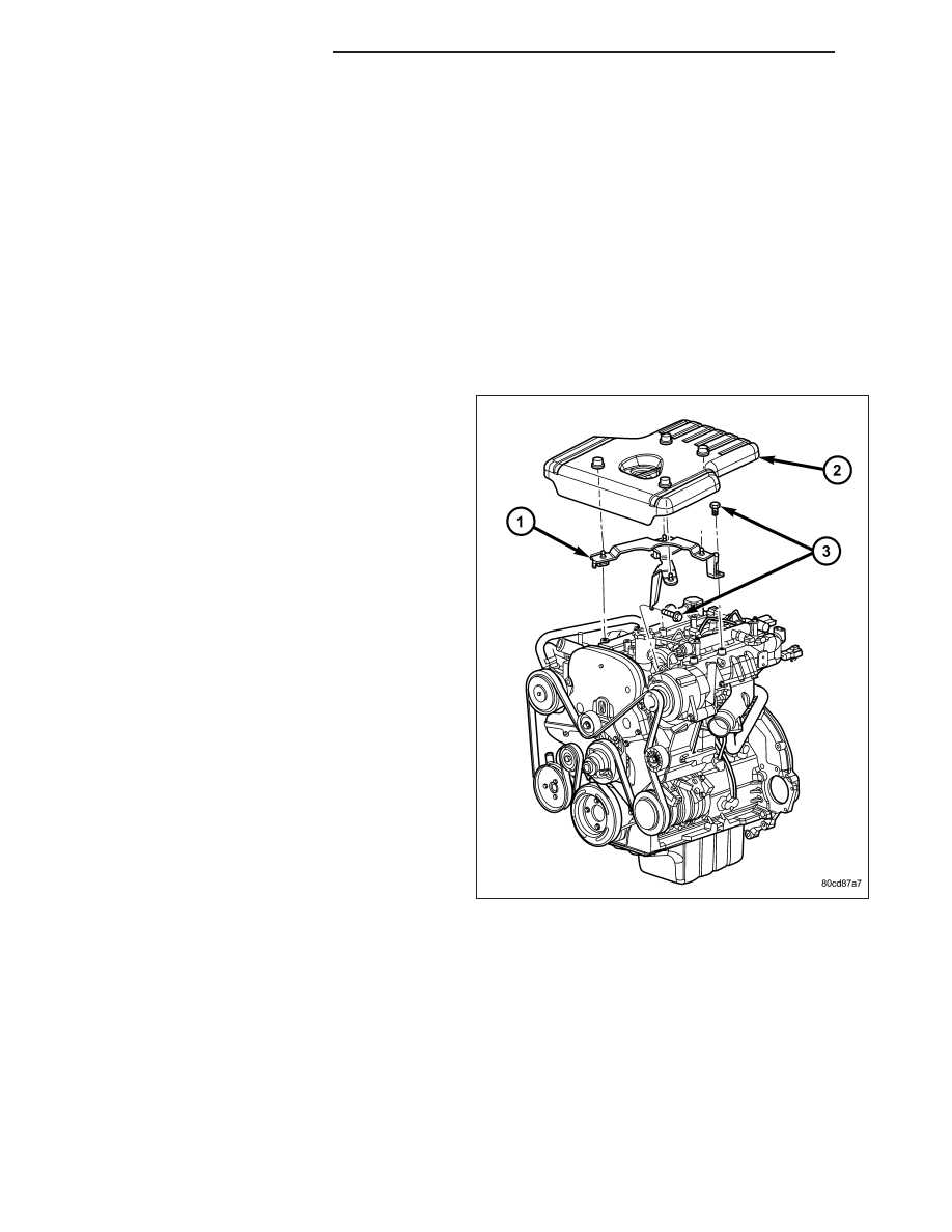
ENGINE COVER

1. Remove oil fill cap.

2. Carefully lift engine cover (2) from corners to

remove from mounting bracket (1)..

INSTALLATION

ENGINE - 2.8L DIESEL

1. Install engine assembly and align with the transmission.

NOTE: For vehicle equipped with a manual transmission, Install the transmission.

2. Raise and support the vehicle.

3. Install accessable engine to transmission housing bolts. tighten bolts to 68 N·m (50 ft. lbs.).

4. Connect oil pressure sensor, located between the engine block and the turbocharger.

5. Connect crankshaft position sensor, located on the right rear of the engine.

6. Install right side engine mount on the engine block.

9 - 1590

ENGINE - 2.8L DIESEL

KJ

7. Disconnect lifting device from the engine assembly.

8. Raise and support the vehicle.

9. Install all transmission to engine retaining bolts.

10. Install exhaust inlet pipe and retaining bolts.

11. Install chassis ground wire above starter mounting location on the engine block.

12. Install starter motor on the engine.

13. Install oil filter and cooler assembly.

14. Lower vehicle.

15. Install oil cooler adapter.

16. Install coolant elbow and retaining bolts and connect the hoses leading from it.

17. Trace engine wiring and connect electrical connectors and tie straps one at a time until all wiring is connected

on engine assembly.

18. Install low side refrigerant line.

19. Install generator on the engine (Refer to 8 - ELECTRICAL/CHARGING/GENERATOR - INSTALLATION).

20. Connect heater core inlet and outlet hoses at heater core.

21. Connect four large electrical connectors near rear of the right front fenderwell.

22. Install engine cover mounting bracket and retaining bolts.

23. Accessing bolts through the pump pulley, install the power steering pump and retaining bolts.

24. Install accessory drive belt (Refer to 7 - COOLING/ACCESSORY DRIVE/DRIVE BELTS - INSTALLATION).

25. Install coolant reservoir and connect hoses.

26. Install coolant reservoir retaining nuts.

27. Install high side refrigerant line on compressor.

28. Install charge air cooler hose on intake manifold.

29. Install cooling module assembly in the engine bay.

30. Install power steering cooler and retaining bolts and clip the air deflectors on both sides of the radiator (cooling

module) assembly.

31. Install condenser assembly and retaining bolts.

32. Install low side refrigerant line and retaining nut.

33. Connect coolant reservoir hose on radiator.

34. Connect engine coolant hoses on engine.

35. Connect charge air cooler hoses on charge air cooler.

36. Install fan shroud with cooling fan assembly inside the shroud and install the shroud retaining bolts.

37. Connect cooling fan and fan drive viscous clutch assembly to fan support.

38. Install high side refrigerant line and retaining nut.

39. Install upper radiator support bracket and retaining bolts.

40. Connect high side refrigerant line on the upper radiator support bracket.

41. Charge refrigerant system (Refer to 24 - HEATING & AIR CONDITIONING/PLUMBING - STANDARD PROCE-

DURE).

42. Install air filter assembly.

43. Install engine cover (Refer to 9 - ENGINE COVER - REMOVAL).

44. Install engine oil fill cap.

45. Fill cooling system (Refer to 7 - COOLING/ENGINE/COOLANT - STANDARD PROCEDURE).

46. With assistance from another person, install hood assembly on the vehicle.

47. Connect under hood lamp on the hood assembly.

48. Connect negative battery cable.

KJ

ENGINE - 2.8L DIESEL

9 - 1591

ENGINE COVER

1. Align engine cover (2) with mounting bracket (1).

Push down firmly on all four corners of engine
cover to snap in place.

2. Install oil fill cap.

SPECIFICATIONS

ENGINE SPECIFICATIONS

GENERAL DESCRIPTION

DESCRIPTION

SPECIFICATION

Engine Type

R2816K5A

Weight

270Kg (595 lbs.) dry

Number of Cylinders

4

Bore

94 mm

Stroke

100 mm

Displacement

2776cc

Injection Order

1-3-4-2

Compression Ratio

17.5:1 (± 0.5)

Maximum Power

120 kW (163 H.P.) @ 3800 RPM

Peak Torque

400 N·m (295 ft.lb.) @ 1800 RPM

Cylinder Compression (Max. Difference Between

Cylinders

5 Bar (72.5 psi)

Minimum Oil Pressure (Warm)

0.7 Bar (10 psi.) @ Idle

2 Bar (29 psi.) @ 3800 RPM

CRANKSHAFT

9 - 1592

ENGINE - 2.8L DIESEL

KJ

DESCRIPTION

SPECIFICATION

Metric

Standard

Front Journal Diameter-Nominal

62.985-63.005 mm

2.479-2.480 in

Front Journal Diameter- minus 0.25

62.735-62.755 mm

2.469-2.470 in.

Front Bearing Diameter-Nominal

63.005-63.034 mm

2.480-2.481 in.

Front Bearing Diameter-minus 0.25

62.755-62.784 mm

2.471-2.478 in

Clearance Between the Journal and

Bearing

0.00-0.049 mm

0.000-0.001 in.

Center Journal Diameter-Nominal

63.005-63.020 mm

0.001-0.003 in.

Center Journal Diameter-minus 0.25

62.775-62.770 mm

2.470-2.471

Center Bearing Diameter-Nominal

63.005-63.020 mm

2.480-2.481 in.

Center Bearing Diameter-minus

0.25

62.775-62.770 mm

2.470-2.471 in.

Clearance Between Journal and

Bearing

0.008-0.051 mm

0.0003-0.0002 in

Rear Journal Diameter-Nominal

89.980-90.000 mm

3.542-3.543 in

Rear Journal Diameter- minus 0.25

89.730-99.750 mm

3.532-3.927 in.

Rear Bearing Diameter-Nominal

90.045-90.065 mm

3.545-3.546 in.

Rear Bearing Diameter- minus 0.25

89.795-89.815 mm

3.535-3.536 in.

Clearance Between Journal and

Bearing

0.045-0.080 mm

0.001-0.003 in.

Connecting Rod Journal-Nominal

53.940-53.955 mm

2.123-2.124 in.

Connecting Rod Journal- minus

0.25

53.690-53.705 mm

2.113-2.114 in.

Connecting Rod Bearing-Nominal

53.997-54.016 mm

2.125-2.126 in.

Connecting Rod Bearing- minus

0.25

53.727-53.766 mm

2.115-2.116 in.

Clearance Between Journal and

Bearing

0.022-0.076 mm

0.0008-0.0029 in.

Crankshaft End Play

0.080-0.280 mm

0.003-0.011 in.

Adjustment

Thrust Washers

Thrust Washers

Thrust Washers Available

2.31-2.36 mm

0.090-0.092 in.

2.41-2.46 mm

0.094-0.096 in.

2.51-2.56 mm

0.098-0.100

Carrier with Thrush Washers

Installed

27.670-27.820 mm

1.089-1.095 in.

MAIL BEARING CARRIERS

DESCRIPTION

SPECIFICATION

Metric

Standard

Internal Diameter-Front

67.025-67.050 mm

2.638-2.639 in.

Internal Diameter-Center

66.670-66.690 mm

2.624-2.624 in.

Internal Diameter-Rear

85.985-86.005 mm

3.385-3.386 in.

LINERS

KJ

ENGINE - 2.8L DIESEL

9 - 1593


Content   ..  906  907  908  909   ..