Jeep Liberty KJ. Manual - part 896


  Index      Jeep     Jeep Liberty KJ - service repair manual 2006 year


Search            


Content   ..  894  895  896  897   ..


Jeep Liberty KJ. Manual - part 896


MOUNT-REAR

REMOVAL

NOTE: A resilient rubber cushion supports the transmission at the rear between the transmission extension
housing and the rear support crossmember or skid plate.

1. Disconnect negative cable from battery.

2. Raise the vehicle and support the transmission.

3. Remove the nuts holding the support cushion to the crossmember. Remove the crossmember.

MANUAL TRANSMISSION

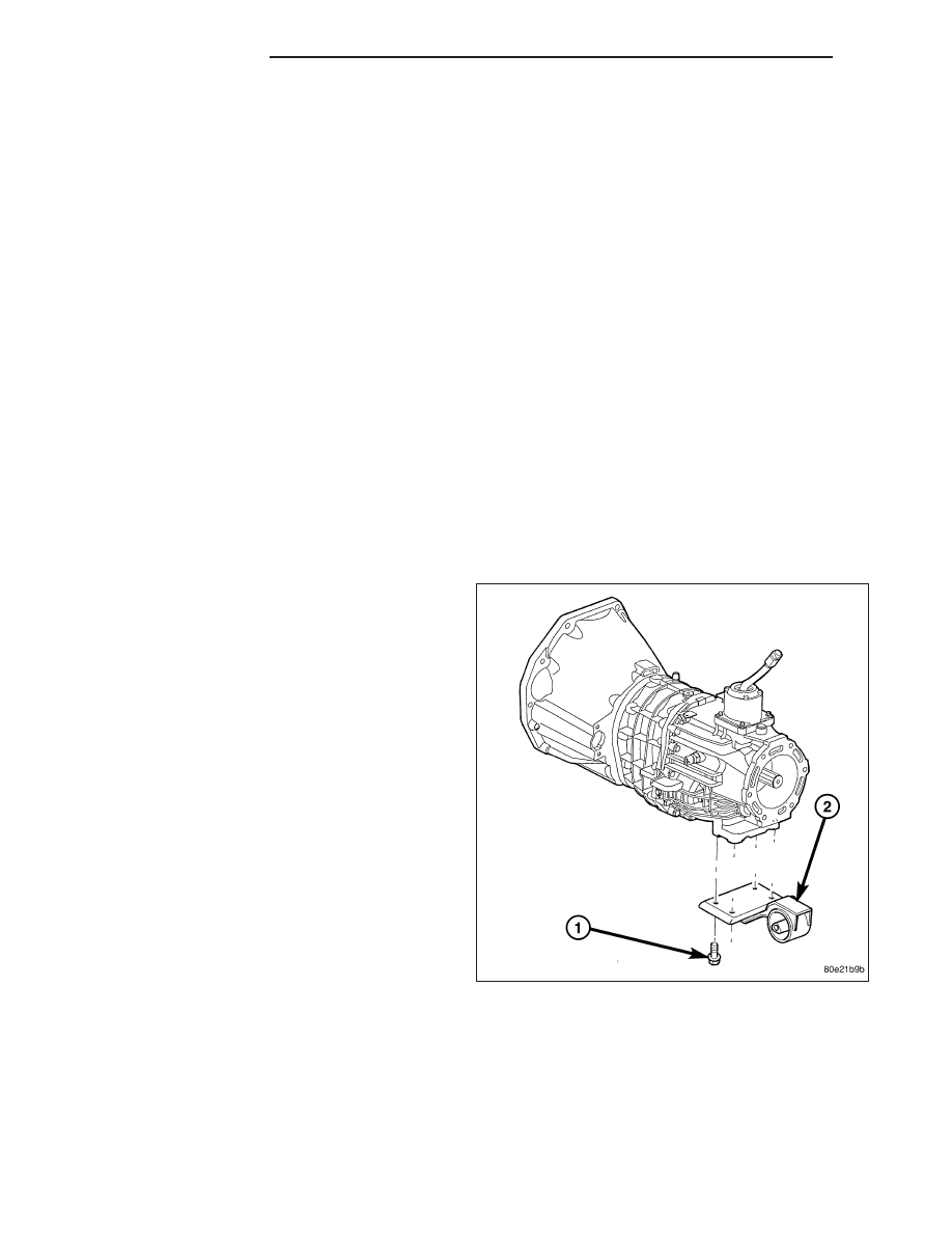
a. Remove the support cushion nuts and remove the cushion.

b. Remove the transmission support bracket bolts and remove the bracket from the transmission.

AUTOMATIC TRANSMISSION

a. Remove the support cushion bolts and remove the cushion and the support bracket from the transmission
(4WD) or from the adaptor bracket (2WD).

b. On 2WD vehicles, remove the bolts holding the transmission support adaptor bracket to the transmission.
Remove the adaptor bracket.

INSTALLATION

MANUAL TRANSMISSION:

9 - 1542

ENGINE - 3.7L

KJ

1. Install the transmission mount (1) to the transmis-

sionor. Install the bolts (2) and tighten.

2. Position the crossmember in the vehicle. Install the crossmember to mount through bolt and nut.

3. Install crossmember-to-sill bolts and tighten to 41 N·m (30 ft. lbs.) torque.

4. Remove the transmission support.

5. Lower the vehicle.

6. Connect negative cable to battery.

AUTOMATIC TRANSMISSION:

KJ

ENGINE - 3.7L

9 - 1543

1. Install the transmission mount to transmission and.

Install the bolts.

2. Position the crossmember in the vehicle. Install the

crossmember to mount through bolt and nut.

3. Remove the transmission support.

4. Lower the vehicle.

5. Connect negative cable to battery.

9 - 1544

ENGINE - 3.7L

KJ

LUBRICATION

DESCRIPTION

The lubrication system is a full flow filtration pressure feed type.

OPERATION

Engine Lubrication Flow Chart - Block: Table 1

FROM

TO

Oil Pickup Tube

Oil Pump

Oil Pump

Oil Filter

Oil Filter

Block Main Oil Gallery

Block Main Oil Gallery

1. Crankshaft Main Journal

2. Left Cylinder Head*

3. Right Cylinder Head*

4. Counterbalance Shaft Rear Journal

Crankshaft Main Journals

Crankshaft Rod Journals

Crankshaft Number One Main Journal

1. Front Timing Chain Idler Shaft

2. Counterbalance Shaft - Front Journal

3. Both Secondary Chain Tensioners

Left Cylinder Head

Refer to Engine Lubrication Flow Chart - Cylinder
Heads: Table 2

Right Cylinder Head

Refer to Engine Lubrication Flow Chart - Cylinder
Heads: Table 2

* The cylinder head gaskets have an oil restricter to control oil flow to the cylinder heads

Engine Lubrication Flow Chart - Cylinder Heads: Table 2

FROM

TO

Cylinder Head Oil Port (in bolt hole)

Diagonal Cross Drilling to Main Oil Gallery

Main Oil Gallery (drilled through head from rear to front)

1. Base of Camshaft Towers

2. Lash Adjuster Towers

Base of Camshaft Towers

Vertical Drilling Through Tower to Camshaft Bearings**

Lash Adjuster Towers

Diagonal Drillings to Hydraulic Lash Adjuster Pockets

** The number three camshaft bearing journal feeds oil into the hollow camshaft tubes. Oil is routed to the intake
lobes, which have oil passages drilled into them to lubricate the rocker arms.

KJ

ENGINE - 3.7L

9 - 1545


Content   ..  894  895  896  897   ..