Jeep Liberty KJ. Manual - part 885


  Index      Jeep     Jeep Liberty KJ - service repair manual 2006 year


Search            


Content   ..  883  884  885  886   ..


Jeep Liberty KJ. Manual - part 885


6. Tighten the bolts in sequence using the following steps and torque values :

Step 1: Tighten bolts 1-8, 27 N·m (20 ft. lbs.).

Step 2: Verify that bolts 1-8, all reached 27 N·m (20 ft. lbs.), by repeating step 1 without loosening the bolts.
Tighten bolts 9 thru 12 to 14 N·m (10 ft. lbs.).

Step 3: Tighten bolts 1-8, 90 °.

Step 4: Tighten bolts 1-8, 90 °, again. Tighten bolts 9-12, 26 N·m (19 ft. lbs.)

CAUTION: The nut on the right side camshaft
sprocket should not be removed for any reason,
as the sprocket and camshaft sensor target wheel
is serviced as an assembly. If the nut was
removed, torque nut to 5 NM ( 60 in. lbs.).

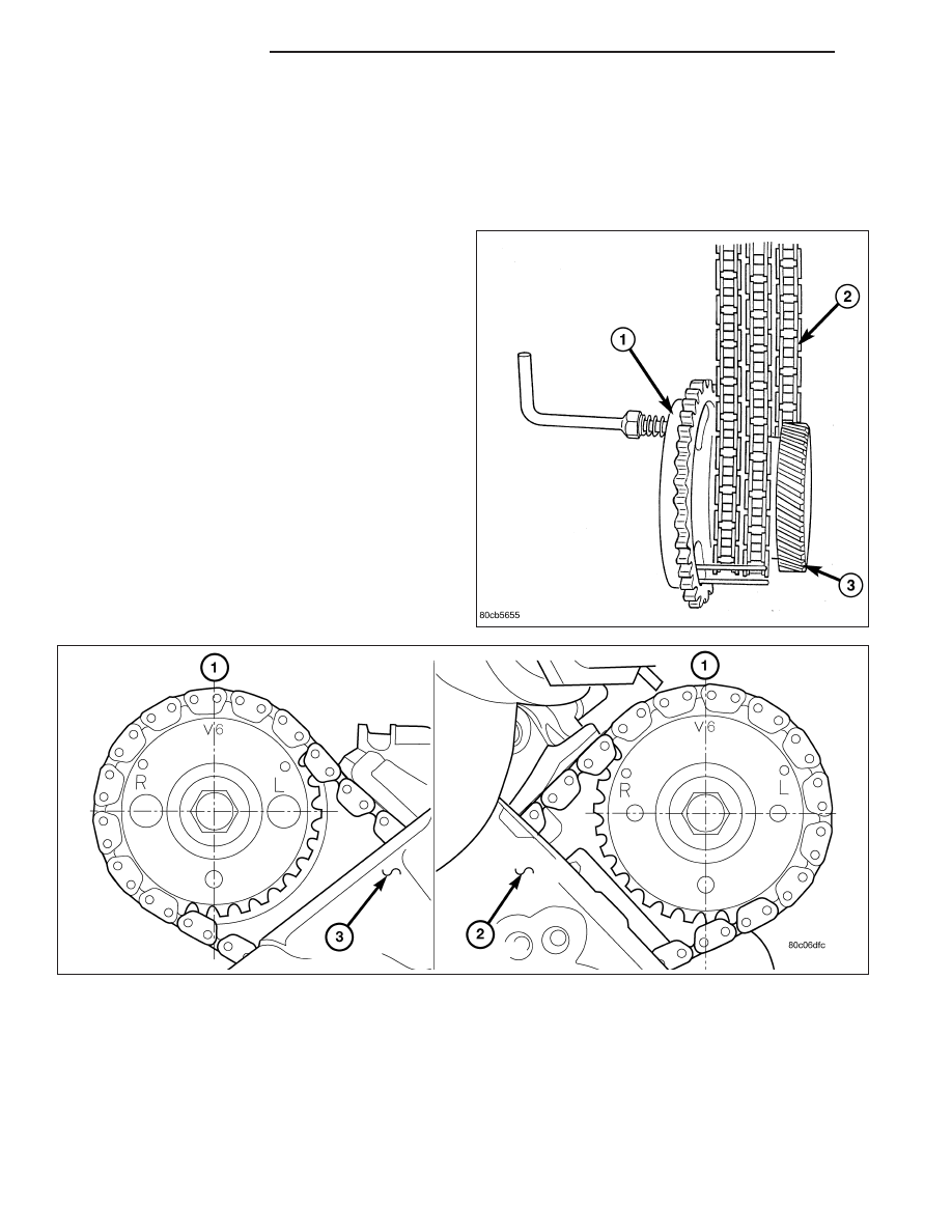
7. Position the secondary chain (2) onto the camshaft

drive gear, making sure one marked chain link is
on either side of the V6 mark (1) on the gear then
using Special Tool 8428 Camshaft Wrench, position
the gear onto the camshaft.

CAUTION:

Remove

excess

oil

from

camshaft

sprocket retaining bolt before reinstalling bolt.
Failure to do so may cause over-torquing of bolt
resulting in bolt failure.

8. Install the camshaft drive gear retaining bolt.

9. Install the right side secondary chain guide (Refer

to 9 - ENGINE/VALVE TIMING/TIMING BELT/
CHAIN AND SPROCKETS - INSTALLATION).

9 - 1498

ENGINE - 3.7L

KJ

10. Install the cylinder head access plug (1,2).

11. Re-set and install the right side secondary chain

tensioner (Refer to 9 - ENGINE/VALVE TIMING/
TIMING

BELT/CHAIN

AND

SPROCKETS

-

INSTALLATION).

12. Remove Special Tool 8429 (1).

13. Install the timing chain cover (Refer to 9 -

ENGINE/VALVE TIMING/TIMING BELT / CHAIN
COVER(S) - REMOVAL).

14. Install the crankshaft damper (Refer to 9 -

ENGINE/ENGINE BLOCK/VIBRATION DAMPER -
INSTALLATION). Tighten damper bolt 175 N·m
(130 Ft. Lbs.).

15. Install accessory drive belt (Refer to 7 - COOL-

ING/ACCESSORY

DRIVE/DRIVE

BELTS

-

INSTALLATION).

16. Install the fan shroud (Refer to 7 - COOLING/EN-

GINE/RADIATOR FAN - INSTALLATION).

17. Install the cylinder head cover (Refer to 9 -

ENGINE/CYLINDER

HEAD/CYLINDER

HEAD

COVER(S) - INSTALLATION).

18. Install the intake manifold (Refer to 9 - ENGINE/

MANIFOLDS/INTAKE MANIFOLD - INSTALLA-
TION).

19. Install oil fill housing onto cylinder head.

20. Refill the cooling system (Refer to 7 - COOLING -

STANDARD PROCEDURE).

21. Raise the vehicle.

22. Install the exhaust pipe onto the right exhaust manifold.

23. Lower the vehicle.

24. Reconnect battery negative cable.

25. Start the engine and check for leaks.

KJ

ENGINE - 3.7L

9 - 1499

CAMSHAFT

DESCRIPTION

The camshafts consist of powdered metal steel lobes which are sinter-bonded to a steel tube. Four bearing journals
are machined into the camshaft. Camshaft end play is controlled by two thrust walls that border the nose piece
journal.

REMOVAL

CAUTION: When the timing chain is removed and the cylinder heads are still installed, DO NOT forcefully
rotate the camshafts or crankshaft independently of each other. Severe valve and/or piston damage can
occur.

CAUTION: When removing the cam sprocket, timing chains or camshaft, Failure to use special tool 8379 will
result in hydraulic tensioner ratchet over extension, Requiring timing chain cover removal to re-set the ten-
sioner ratchet.

1. Remove the cylinder head cover (Refer to 9 - ENGINE/CYLINDER HEAD/CYLINDER HEAD COVER(S) -

REMOVAL).

2. Set engine to TDC cylinder No. 1, camshaft sprocket V6 marks at the 12 o’clock position (1).

3. Mark one link on the secondary timing chain on both sides of the V6 mark on the camshaft sprocket to aid in

installation.

9 - 1500

ENGINE - 3.7L

KJ

CAUTION: Do not hold or pry on the camshaft tar-
get wheel for any reason, Severe damage will
occur to the target wheel. A damaged target wheel
could cause a vehicle no start condition.

4. Loosen but DO NOT remove the camshaft sprocket

retaining bolt. Leave bolt snug against sprocket.

NOTE: The timing chain tensioners must be
secured prior to removing the camshaft sprockets.
Failure to secure tensioners will allow the tension-
ers

to

extend,

requiring

timing

chain

cover

removal in order to reset tensioners.

CAUTION: Do not force wedge past the narrowest
point between the chain strands. Damage to the
tensioners may occur.

5. Position Special Tool 8379 timing chain wedge (1)

between the timing chain strands. Tap the tool to
securely wedge the timing chain against the ten-
sioner arm and guide.

KJ

ENGINE - 3.7L

9 - 1501


Content   ..  883  884  885  886   ..