Jeep Liberty KJ. Manual - part 723


  Index      Jeep     Jeep Liberty KJ - service repair manual 2006 year


Search            


Content   ..  721  722  723  724   ..


Jeep Liberty KJ. Manual - part 723


3.

ASD OUTPUT CKT OPEN

Turn the ignition off.

Disconnect the EGR Solenoid harness connector.

Turn the ignition on.

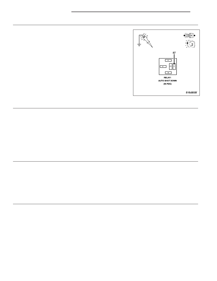
Using a 12-volt test light connected to ground, check the ASD Relay
Output circuit.

Does the test light illuminate brightly?

Yes

>> Go To 4

No

>> Repair the ASD Relay Output circuit for an open.

Perform the ECM Verification Test Ver. 1 (Refer to 9 -
ENGINE - DIAGNOSIS AND TESTING).

4.

(K35) EGR SOLENOID CONTROL CIRCUIT SHORTED TO GROUND

Turn the ignition off.

Disconnect the EGR Solenoid harness connector.

Disconnect the ECM harness connectors.

Measure the resistance between ground and the (K35) EGR Solenoid Control circuit.

Is the resistance above 1000 ohms?

Yes

>> Go To 5

No

>> Repair the (K35) EGR Solenoid Control circuit for a short to ground.

Perform the ECM Verification Test Ver. 1 (Refer to 9 - ENGINE - DIAGNOSIS AND TESTING).

5.

(K35) EGR SOLENOID CONTROL CIRCUIT OPEN

Measure the resistance of the (K35) EGR Solenoid Control circuit between the EGR Solenoid harness connector
and the ECM C1 harness connector.

Is the resistance below 10.0 ohms?

Yes

>> Go To 6

No

>> Repair the (K35) EGR Solenoid Control circuit for an open.

Perform the ECM Verification Test Ver. 1 (Refer to 9 - ENGINE - DIAGNOSIS AND TESTING).

6.

EGR SOLENOID

Install a substitute EGR Solenoid in place of the vehicle’s EGR Solenoid.

NOTE: Ensure the ECM and EGR Solenoid harness connectors are connected.
Turn the ignition on.

With the scan tool, check for this DTC to set again.

Did this DTC set again?

Yes

>> Replace and program the Engine Control Module in accordance with the Service Information.

Perform the ECM Verification Test Ver. 1 (Refer to 9 - ENGINE - DIAGNOSIS AND TESTING).

No

>> Replace the EGR Solenoid.

Perform the ECM Verification Test Ver. 1 (Refer to 9 - ENGINE - DIAGNOSIS AND TESTING).

9 - 950

ENGINE DIESEL DIAG

KJ

P0460-FUEL LEVEL SENSOR CIRCUIT SIGNAL VOLTAGE TOO HIGH

For a complete wiring diagram Refer to Section 8W

KJ

ENGINE DIESEL DIAG

9 - 951

When Monitored:
With the ignition on.

Set Condition:
The Fuel Level Sensor signal voltage is above 4.51 volts for 1.0 seconds.

Possible Causes

INTERMITTENT CONDITION

(K304) FUEL LEVEL SENSOR SIGNAL CIRCUIT SHORTED TO VOLTAGE

(K304) FUEL LEVEL SENSOR SIGNAL CIRCUIT OPEN

(K300) FUEL LEVEL SENSOR GROUND CIRCUIT OPEN

FUEL PUMP MODULE

BODY CONTROL MODULE

Diagnostic Test

1.

CHECK FOR ACTIVE DTC

NOTE: If the ECM detects and stores a DTC, the ECM also stores the engine/vehicle operating conditions
under which the DTC was set. Some of these conditions are displayed on the scan tool at the same time the
DTC is displayed.

NOTE: Before erasing stored DTCs, record these conditions. Attempting to duplicate these conditions may
assist when checking for an active DTC.
Turn the ignition on.

With the scan tool, erase ECM DTCs.

Turn the ignition off, wait 10 seconds, then turn the ignition on.

With the scan tool, read ECM DTCs.

Did this DTC set again?

Yes

>> Go To 2

No

>> Refer to the *CHECKING FOR AN INTERMITTENT DTC Diagnostic Procedure. (Refer to 9 - ENGINE -

DIAGNOSIS AND TESTING)

2.

(K304) FUEL LEVEL SENSOR SIGNAL CIRCUIT SHORTED TO VOLTAGE

Turn the ignition off.

Disconnect the BCM harness connectors.

Disconnect the Fuel Pump Module harness connector.

Remove the ASD Relay from the PDC.

Connect a jumper wire between cavity 30 and cavity 87 of the ASD
Relay connector.

Turn the ignition on.

Measure the voltage on the (K304) Fuel Level Sensor Signal circuit.

Is the voltage below 0.5 volt?

Yes

>> Go To 3

No

>> Repair the (K304) Fuel Level Sensor Signal circuit for a

short to voltage.

Perform the ECM Verification Test Ver. 1 (Refer to 9 -
ENGINE - DIAGNOSIS AND TESTING).

9 - 952

ENGINE DIESEL DIAG

KJ

3.

(K304) FUEL LEVEL SENSOR SIGNAL CIRCUIT OPEN

Turn the ignition off.

Measure the resistance of the (K304) Fuel Level Sensor Signal circuit
from the Fuel Pump Module harness connector to the BCM harness
connector.

Is the resistance below 10.0 ohms?

Yes

>> Go To 4

No

>> Repair the (K304) Fuel Level Sensor Signal circuit for an

open.

Perform the ECM Verification Test Ver. 1 (Refer to 9 -
ENGINE - DIAGNOSIS AND TESTING).

4.

FUEL LEVEL SENSOR GROUND CIRCUIT OPEN

Measure the resistance of the (K300) Fuel Level Sensor Ground circuit
from the Fuel Pump Module harness connector to the BCM harness
connector.

Is the resistance below 10.0 ohms?

Yes

>> Go To 5

No

>> Repair the (K300) Fuel Level Sensor Ground circuit for an

open.

Perform the ECM Verification Test Ver. 1 (Refer to 9 -
ENGINE - DIAGNOSIS AND TESTING).

KJ

ENGINE DIESEL DIAG

9 - 953


Content   ..  721  722  723  724   ..