Jeep Liberty KJ. Manual - part 612


  Index      Jeep     Jeep Liberty KJ - service repair manual 2006 year


Search            


Content   ..  610  611  612  613   ..


Jeep Liberty KJ. Manual - part 612


3.

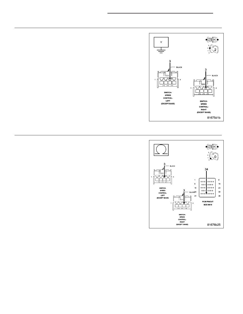
(V37) S/C SWITCH NO.1 SIGNAL CIRCUIT SHORTED TO BATTERY VOLTAGE

Turn the ignition off.

Disconnect the C3 PCM harness connector.

Measure the voltage of the (V37) S/C Switch No.1 Signal circuit in the
Speed Control harness connector.

Is the voltage above 5.0 volts?

Yes

>> Repair the short to battery voltage in the (V37) S/C Signal

No.1 circuit.

Perform the POWERTRAIN VERIFICATION TEST. (Refer to
9 - ENGINE - STANDARD PROCEDURE)

No

>> Go To 4

4.

(V37) S/C SWITCH NO.1 SIGNAL CIRCUIT OPEN

NOTE: The measurement must be taken from both Speed Control
Switch harness connectors.
Turn the ignition off.

CAUTION: Do not probe the PCM harness connectors. Probing the
PCM harness connectors will damage the PCM terminals resulting
in poor terminal to pin connection. Install Miller Special Tool #8815
to perform diagnosis.
Measure the resistance of the (V37) S/C Switch No.1 Signal circuit from
the Speed Control harness connector to the appropriate terminal of spe-
cial tool #8815.

Is the resistance below 5.0 ohms for both measurements?

Yes

>> Go To 5

No

>> Repair the open in the (V37) S/C Switch No.1 Signal circuit.

Perform the POWERTRAIN VERIFICATION TEST. (Refer to
9 - ENGINE - STANDARD PROCEDURE)

9 - 506

ENGINE ELECTRICAL DIAGNOSTICS

KJ

5.

(K900) SENSOR GROUND CIRCUIT OPEN

NOTE: The measurement must be taken from both Speed Control
Switch harness connectors.
Disconnect the C2 PCM harness connector.

Measure the resistance of the (K900) Sensor ground circuit from the
Speed Control harness connector to the appropriate terminal of special
tool #8815.

Is the resistance below 5.0 ohms for both measurements?

Yes

>> Go To 6

No

>> Repair the open in the (K900) Sensor ground circuit.

Perform the POWERTRAIN VERIFICATION TEST. (Refer to
9 - ENGINE - STANDARD PROCEDURE)

6.

(V37) S/C SWITCH NO.1 SIGNAL CIRCUIT SHORTED TO GROUND

Measure the resistance between ground and the (V37) S/C Switch No.1
Signal circuit in the Speed Control harness connector.

Is the resistance below 100 ohms?

Yes

>> Repair the short to ground in the (V37) S/C Switch No.1

Signal circuit.

Perform the POWERTRAIN VERIFICATION TEST. (Refer to
9 - ENGINE - STANDARD PROCEDURE)

No

>> Go To 7

KJ

ENGINE ELECTRICAL DIAGNOSTICS

9 - 507

7.

(V37) S/C SWITCH NO.1 SIGNAL CIRCUIT SHORTED TO THE (K900) SENSOR GROUND CIRCUIT

Measure the resistance between the (V37) S/C Switch No.1 Signal cir-
cuit and the (K900) Sensor ground circuit in the Speed Control harness
connector.

Is the resistance below 5.0 ohms?

Yes

>> Repair the short between the (V37) S/C Switch No.1 Signal

circuit and the (K900) Sensor ground circuit.

Perform the POWERTRAIN VERIFICATION TEST. (Refer to
9 - ENGINE - STANDARD PROCEDURE)

No

>> Go To 8

8.

PCM

NOTE: Before continuing, check the PCM harness connector terminals for corrosion, damage, or terminal
push out. Repair as necessary.
Using the schematics as a guide, inspect the wire harness and connectors. Pay particular attention to all Power and
Ground circuits.

Were there any problems found?

Yes

>> Repair as necessary.

Perform the POWERTRAIN VERIFICATION TEST. (Refer to 9 - ENGINE - STANDARD PROCEDURE)

No

>> Replace and program the Powertrain Control Module per Service Information.

Perform the POWERTRAIN VERIFICATION TEST. (Refer to 9 - ENGINE - STANDARD PROCEDURE)

9 - 508

ENGINE ELECTRICAL DIAGNOSTICS

KJ

P1602–PCM NOT PROGRAMMED

For a complete wiring diagram Refer to Section 8W.

When Monitored:
Ignition on and battery voltage greater than 10 volts.

Set Condition:
The PCM has not been programmed.

Possible Causes

PCM

Always perform the Pre-Diagnostic Troubleshooting procedure before proceeding. (Refer to 9 - ENGINE -
DIAGNOSIS AND TESTING).

Diagnostic Test

1.

PCM PROGRAMMED

Ignition on, engine not running.

With a scan tool, erase DTCs.

With a scan tool program the PCM.

Start the engine.

Allow the engine to reach normal operating temperature.

With a scan tool, read DTCs.

Does the DTC reset?

Yes

>> Replace and program the Powertrain Control Module per Service Information.

Perform the POWERTRAIN VERIFICATION TEST. (Refer to 9 - ENGINE - STANDARD PROCEDURE)

No

>> The PCM has been successfully programmed. Test is complete.

Perform the POWERTRAIN VERIFICATION TEST. (Refer to 9 - ENGINE - STANDARD PROCEDURE)

KJ

ENGINE ELECTRICAL DIAGNOSTICS

9 - 509


Content   ..  610  611  612  613   ..