Jeep Liberty KJ. Manual - part 583


  Index      Jeep     Jeep Liberty KJ - service repair manual 2006 year


Search            


Content   ..  581  582  583  584   ..


Jeep Liberty KJ. Manual - part 583


3.

(F1) FUSED IGNITION SWITCH OUTPUT CIRCUIT

Ignition on, engine not running.

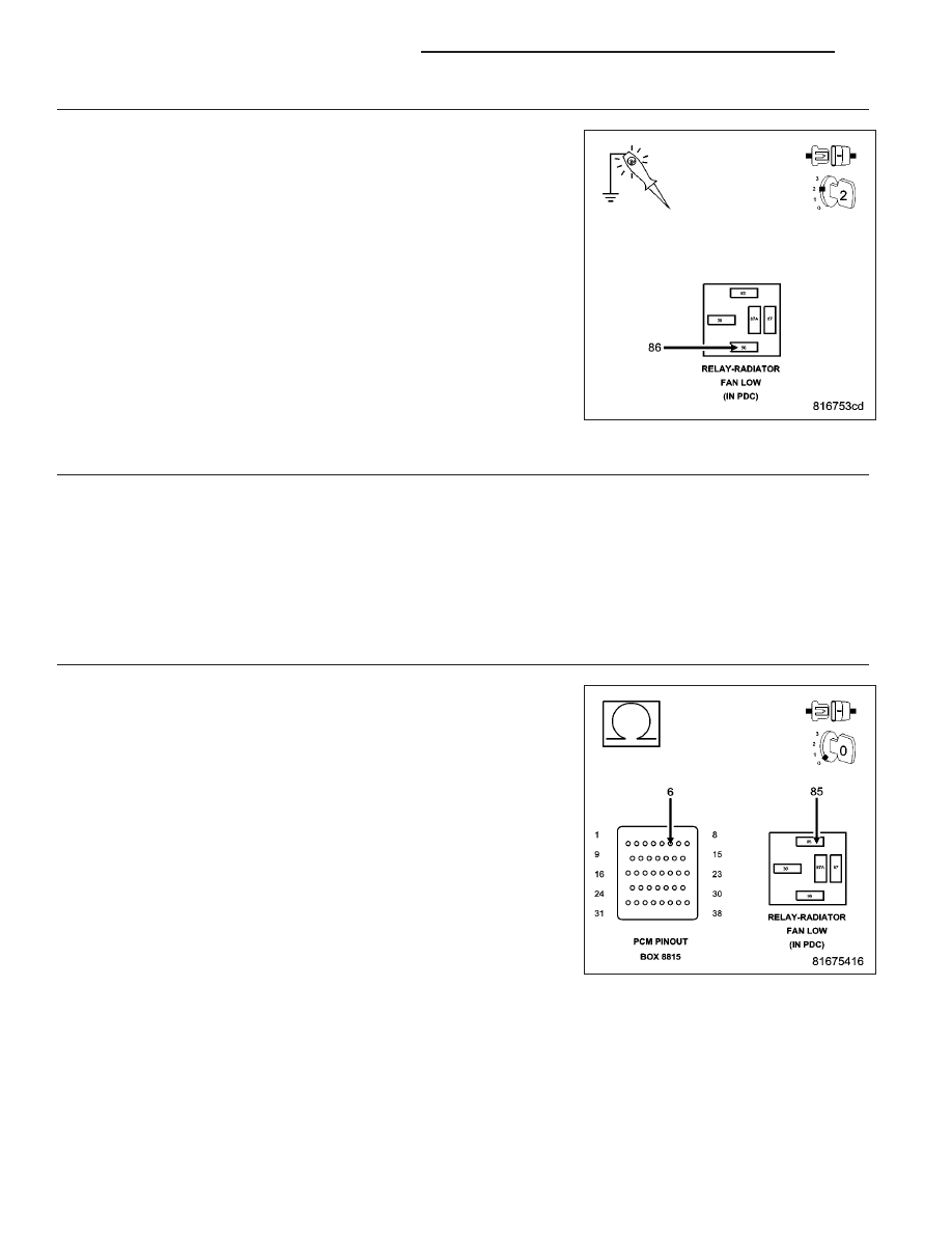
Using a 12-volt test light connected to ground, probe the (F1) Fused
Ignition Switch Output circuit.

Does the test light illuminate brightly?

Yes

>> Go To 4

No

>> Repair the open or short to ground in the (F1) Fused Igni-

tion Output circuit. Inspect the related fuse and repair as
necessary.

Perform the POWERTRAIN VERIFICATION TEST. (Refer to
9 - ENGINE - STANDARD PROCEDURE)

4.

LOW SPEED RADIATOR FAN RELAY RESISTANCE

Turn the ignition off.

Measure the resistance of the Low Speed Radiator Fan Relay Coil.

Is the resistance between 60 to 80 ohms?

Yes

>> Go To 5

No

>> Replace the Low Speed Radiator Fan Relay.

Perform the POWERTRAIN VERIFICATION TEST. (Refer to 9 - ENGINE - STANDARD PROCEDURE)

5.

(N201) COOLING FAN NO.1 CONTROL CIRCUIT OPEN

Disconnect the C3 PCM harness connector.

CAUTION: Do not probe the PCM harness connectors. Probing the
PCM harness connectors will damage the PCM terminals resulting
in poor terminal to pin connection. Install Miller Special Tool #8815
to perform diagnosis
Measure the resistance of the (N201) Cooling Fan No.1 Relay Control
circuit from the Relay to the appropriate terminal of special tool #8815.

Is the resistance below 5.0 ohms?

Yes

>> Go To 6

No

>> Repair the open in the (N201) Cooing Fan No.1 Relay Con-

trol circuit.

Perform the POWERTRAIN VERIFICATION TEST. (Refer to
9 - ENGINE - STANDARD PROCEDURE)

9 - 390

ENGINE ELECTRICAL DIAGNOSTICS

KJ

6.

(N201) COOLING FAN NO.1 CONTROL CIRCUIT SHORTED TO GROUND

Measure the resistance between ground and the (N201) Cooling Fan
No.1 Relay Control circuit at the Relay connection.

Is the resistance below 100 ohms?

Yes

>> Repair the short to ground in the (N201) Cooling Fan No.1

Relay Control circuit.

Perform the POWERTRAIN VERIFICATION TEST. (Refer to
9 - ENGINE - STANDARD PROCEDURE)

No

>> Go To 7

7.

PCM

NOTE: Before continuing, check the PCM harness connector terminals for corrosion, damage, or terminal
push out. Repair as necessary.
Using the schematics as a guide, inspect the wire harness and connectors. Pay particular attention to all Power and
Ground circuits.

Were there any problems found?

Yes

>> Repair as necessary.

Perform the POWERTRAIN VERIFICATION TEST. (Refer to 9 - ENGINE - STANDARD PROCEDURE)

No

>> Replace Powertrain Control Module per Service Information.

Perform the POWERTRAIN VERIFICATION TEST. (Refer to 9 - ENGINE - STANDARD PROCEDURE)

KJ

ENGINE ELECTRICAL DIAGNOSTICS

9 - 391

P0498-NVLD CANISTER VENT VALVE SOLENOID CIRCUIT LOW

For a complete wiring diagram Refer to Section 8W.

9 - 392

ENGINE ELECTRICAL DIAGNOSTICS

KJ

When Monitored:
Engine running.

Set Condition:
The PCM detects a short in the NVLD Canister vent solenoid circuits for more than 5 seconds. One Trip Fault.
Three good trips to turn off the MIL.

Possible Causes

(K106) NVLD SOLENOID CONTROL CIRCUIT SHORTED TO GROUND

NVLD ASSEMBLY

PCM

Always perform the Pre-Diagnostic Troubleshooting procedure before proceeding. (Refer to 9 - ENGINE -
DIAGNOSIS AND TESTING).

Diagnostic Test

1.

VEHICLE HISTORY AND SERVICE BULLETIN INVESTIGATION

Ignition on, engine not running.

With a scan tool, read DTCs and record the related Freeze Frame data if any DTCs are present.

Whether or not any DTCs are present you will want to check the following items which may assist in repairing the
customer’s complaint successfully.

Check the vehicles repair history.

If the vehicle has a repair history that pertains to the customer’s current complaint, review the repair.

Inspect the vehicle for any aftermarket accessories that may have been installed incorrectly.

Check for any service bulletin(s) related to the customer’s complaint or DTCs.

If a service bulletin applies, follow the instructions per the service bulletin.

Choose the following scenario that best applies.

The service bulletin repaired the customer’s complaint.

Testing complete.

A DTC is present, no service bulletins apply, or the service bulletin didn’t repair the customer’s complaint.

Go To 2.

2.

ACTIVE DTC

Ignition on, engine not running.

With a scan tool, read DTCs.

Is the DTC active at this time?

Yes

>> Go To 3

No

>> Refer to the INTERMITTENT CONDITION Diagnostic Procedure.

Perform the POWERTRAIN VERIFICATION TEST. (Refer to 9 - ENGINE - STANDARD PROCEDURE)

KJ

ENGINE ELECTRICAL DIAGNOSTICS

9 - 393


Content   ..  581  582  583  584   ..