Jeep Liberty KJ. Manual - part 549


  Index      Jeep     Jeep Liberty KJ - service repair manual 2006 year


Search            


Content   ..  547  548  549  550   ..


Jeep Liberty KJ. Manual - part 549


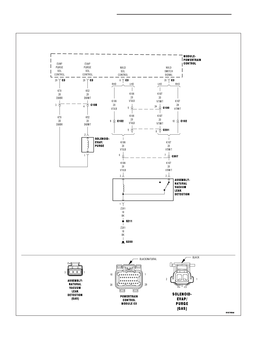
P0453-NVLD PRESSURE SWITCH STUCK OPEN

For a complete wiring diagram Refer to Section 8W.

9 - 354

ENGINE ELECTRICAL DIAGNOSTICS

KJ

When Monitored:
Engine running.

Set Condition:
If the PCM does not see the NVLD switch close during test an error is detected. One Trip Fault. Three good
trips to turn off the MIL.

Possible Causes

(K107) NVLD SWITCH SIGNAL CIRCUIT SHORTED TO BATTERY VOLTAGE

(K107) NVLD SWITCH SIGNAL CIRCUIT OPEN

(K107) NVLD SWITCH SIGNAL CIRCUIT SHORTED TO THE (K106) NVLD SOLENOID CONTROL CIRCUIT

(Z201) GROUND CIRCUIT OPEN

NVLD ASSEMBLY

PCM

Always perform the Pre-Diagnostic Troubleshooting procedure before proceeding. (Refer to 9 - ENGINE -
DIAGNOSIS AND TESTING).

Diagnostic Test

1.

NVLD SWITCH OPERATION

Start the engine.

Allow the engine to idle.

Using a scan tool, perform the NVLD FORCED MONITOR TEST.

Monitor the NVLD Switch state.

NOTE: As the test runs, the NVLD Switch should go from an OPEN state to a CLOSED state and then return
to OPEN when the test is complete.

Did the NVLD Switch operate as described above?

Yes

>> Refer to the INTERMITTENT CONDITION Diagnostic Procedure.

Perform the POWERTRAIN VERIFICATION TEST. (Refer to 9 - ENGINE - STANDARD PROCEDURE)

No

>> Go To 2

2.

NVLD ASSEMBLY

Turn the ignition off.

Disconnect the NVLD electrical harness connector.

Ignition on, engine not running.

Monitor the NVLD Switch state on the scan tool.

Connect a jumper wire between the (K107) NVLD Switch Signal circuit
and the (Z201) Ground circuit in the NVLD harness connector.

Does the Switch change from OPEN to CLOSED with the
jumper wire installed?

Yes

>> Replace the NVLD Assembly.

Perform the POWERTRAIN VERIFICATION TEST. (Refer to
9 - ENGINE - STANDARD PROCEDURE)

No

>> Go To 3

NOTE: Remove the jumper wire before continuing.

KJ

ENGINE ELECTRICAL DIAGNOSTICS

9 - 355

3.

(K107) NVLD SWITCH SIGNAL CIRCUIT SHORTED TO BATTERY VOLTAGE

Turn the ignition off.

Disconnect the C3 PCM harness connector.

Ignition on, engine not running.

Measure the voltage on the (K107) NVLD Switch Signal circuit in the
NVLD electrical harness connector.

Is the voltage above 5.2 volts?

Yes

>> Repair the short to battery voltage in the (K107) NVLD

Switch Signal circuit.

Perform the POWERTRAIN VERIFICATION TEST. (Refer to
9 - ENGINE - STANDARD PROCEDURE)

No

>> Go To 4

4.

(K107) NVLD SWITCH SIGNAL CIRCUIT OPEN

Turn the ignition off.

CAUTION: Do not probe the PCM harness connectors. Probing the
PCM harness connectors will damage the PCM terminals resulting
in poor terminal to pin connection. Install Miller Special Tool #8815
to perform diagnosis.
Measure the resistance of the (K107) NVLD Switch Signal circuit from
the NVLD electrical harness connector to the appropriate terminal of
special tool # 8815.

Is the resistance below 5.0 ohms?

Yes

>> Go To 5

No

>> Repair the open in the (K107) NVLD Switch Signal circuit.

Perform the POWERTRAIN VERIFICATION TEST. (Refer to
9 - ENGINE - STANDARD PROCEDURE)

9 - 356

ENGINE ELECTRICAL DIAGNOSTICS

KJ

5.

(K107) NVLD SWITCH SIGNAL CIRCUIT SHORTED TO THE (K106) NVLD SOLENOID CONTROL CIRCUIT

Measure the resistance between the (K107) NVLD Switch Signal circuit
and the (K106) NVLD Solenoid Control circuit in the NVLD electrical
harness connector.

Is the resistance below 5.0 ohms?

Yes

>> Repair the short between the (K107) NVLD Switch Signal

circuit and the (K106) NVLD Solenoid Control circuit.

Perform the POWERTRAIN VERIFICATION TEST. (Refer to
9 - ENGINE - STANDARD PROCEDURE)

No

>> Go To 6

6.

(Z201) GROUND CIRCUIT OPEN

Measure the resistance between the (Z201) Ground circuit and ground.

Is the resistance below 5.0 ohms?

Yes

>> Go To 7

No

>> Repair the open in the (Z201) Ground circuit.

Perform the POWERTRAIN VERIFICATION TEST. (Refer to
9 - ENGINE - STANDARD PROCEDURE)

7.

PCM

NOTE: Before continuing, check the PCM harness connector terminals for corrosion, damage, or terminal
push out. Repair as necessary.
Using the schematics as a guide, inspect the wire harness and connectors. Pay particular attention to all Power and
Ground circuits.

Were there any problems found?

Yes

>> Repair as necessary.

Perform the POWERTRAIN VERIFICATION TEST. (Refer to 9 - ENGINE - STANDARD PROCEDURE)

No

>> Replace and program the Powertrain Control Module per Service Information.

Perform the POWERTRAIN VERIFICATION TEST. (Refer to 9 - ENGINE - STANDARD PROCEDURE)

KJ

ENGINE ELECTRICAL DIAGNOSTICS

9 - 357


Content   ..  547  548  549  550   ..