Jeep Liberty KJ. Manual - part 536


  Index      Jeep     Jeep Liberty KJ - service repair manual 2006 year


Search            


Content   ..  534  535  536  537   ..


Jeep Liberty KJ. Manual - part 536


8.

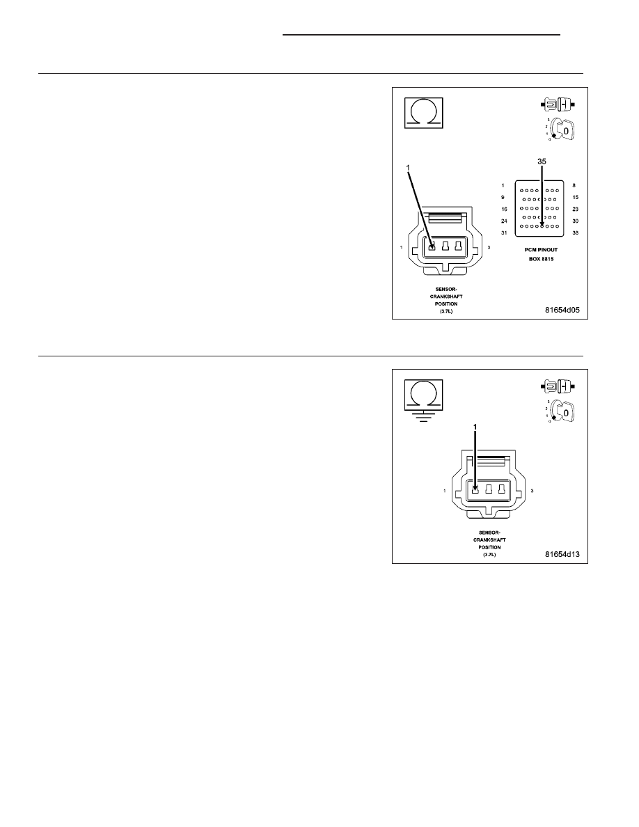
(K24) CKP SIGNAL CIRCUIT OPEN

Turn the ignition off.

CAUTION: Do not probe the PCM harness connectors. Probing the
PCM harness connectors will damage the PCM terminals resulting
in poor terminal to pin connection. Install Miller Special Tool #8815
to perform diagnosis.
Measure the resistance of the (K24) CKP Signal circuit from the CKP
Sensor harness connector to the appropriate terminal of special tool
#8815.

Is the resistance below 5.0 ohms?

Yes

>> Go To 9

No

>> Repair the open in the (K24) CKP Signal circuit.

Perform the POWERTRAIN VERIFICATION TEST. (Refer to
9 - ENGINE - STANDARD PROCEDURE)

9.

(K24) CKP SIGNAL CIRCUIT SHORTED TO GROUND

Measure the resistance between ground and the (K24) CKP Signal cir-
cuit in the CKP Sensor harness connector.

Is the resistance below 5.0 ohms?

Yes

>> Repair the short to ground in the (K24) CKP Signal circuit.

Perform the POWERTRAIN VERIFICATION TEST. (Refer to
9 - ENGINE - STANDARD PROCEDURE)

No

>> Go To 13

9 - 302

ENGINE ELECTRICAL DIAGNOSTICS

KJ

10.

(F855) 5-VOLT SUPPLY CIRCUIT SHORTED TO BATTERY VOLTAGE

Turn the ignition off.

Disconnect the C2 PCM harness connector.

Ignition on, engine not running.

Measure the voltage on the (F855) 5-volt Supply circuit in the CKP Sen-
sor harness connector.

Is the voltage above 5.5 volts?

Yes

>> Repair the short to battery voltage in the (F855) 5-volt Sup-

ply circuit.

Perform the POWERTRAIN VERIFICATION TEST. (Refer to
9 - ENGINE - STANDARD PROCEDURE)

No

>> Go To 11

11.

(F855) 5-VOLT SUPPLY CIRCUIT OPEN

Turn the ignition off.

CAUTION: Do not probe the PCM harness connectors. Probing the
PCM harness connectors will damage the PCM terminals resulting
in poor terminal to pin connection. Install Miller Special Tool #8815
to perform diagnosis.
Measure the resistance of the (F855) 5-volt Supply circuit from the CKP
Sensor harness connector to the appropriate terminal of special tool
#8815.

Is the resistance below 5.0 ohms?

Yes

>> Go To 12

No

>> Repair the open in the (F855) 5-volt Supply circuit.

Perform the POWERTRAIN VERIFICATION TEST. (Refer to
9 - ENGINE - STANDARD PROCEDURE)

KJ

ENGINE ELECTRICAL DIAGNOSTICS

9 - 303

12.

(F855) 5-VOLT SUPPLY CIRCUIT SHORTED TO GROUND

Measure the resistance between ground and the (F855) 5-volt Supply
circuit in the CKP Sensor harness connector.

Is the resistance below 100 ohms?

Yes

>> Repair the short to ground in the (F855) 5-volt Supply cir-

cuit.

Perform the POWERTRAIN VERIFICATION TEST. (Refer to
9 - ENGINE - STANDARD PROCEDURE)

No

>> Go To 13

13.

PCM

NOTE: Before continuing, check the PCM harness connector terminals for corrosion, damage, or terminal
push out. Repair as necessary.
Using the schematics as a guide, inspect the wire harness and connectors. Pay particular attention to all Power and
Ground circuits.

Were any problems found?

Yes

>> Repair as necessary.

Perform the POWERTRAIN VERIFICATION TEST. (Refer to 9 - ENGINE - STANDARD PROCEDURE)

No

>> Replace and program the Powertrain Control Module per Service Information.

Perform the POWERTRAIN VERIFICATION TEST. (Refer to 9 - ENGINE - STANDARD PROCEDURE)

14.

ERRATIC CKP SENSOR SIGNAL

Turn the ignition off.

With a lab scope probe and the Miller special tool #6801, backprobe the (K24) CKP Signal circuit in the CKP har-
nessconnector.

WARNING: When the engine is operating, do not stand in direct line with the fan. Do not put your hands
near the pulleys, belts, or fan. Do not wear loose clothing. Failure to follow these instructions can result in
personal injury or death.
Ignition on, engine not running.

Wiggle the related wire harness and lightly tap on the Crank Position Sensor.

Observe the lab scope screen.

Look for any pulses generated by the CKP Sensor.

Allow the engine to idle.

Observe the lab scope screen.

Did the CKP Sensor generate any erratic pulses?

Yes

>> Inspect the related wire harness and replace the Crankshaft Position Sensor if no wiring problems were

found.

Perform the POWERTRAIN VERIFICATION TEST. (Refer to 9 - ENGINE - STANDARD PROCEDURE)

No

>> Go To 15

9 - 304

ENGINE ELECTRICAL DIAGNOSTICS

KJ

15.

ERRATIC CMP SIGNAL

Turn the ignition off.

With a lab scope probe and the Miller special tool #6801, backprobe the (K44) CMP Signal circuit in the CMP
harness connector.

WARNING: When the engine is operating, do not stand in direct line with the fan. Do not put your hands
near the pulleys, belts, or fan. Do not wear loose clothing. Failure to follow these instructions can result in
personal injury or death.
Ignition on, engine not running.

Wiggle the related wire harness and lightly tap on the Cam Position Sensor.

Observe the lab scope screen.

Look for any pulses generated by the CMP Sensor.

Allow the engine to idle.

Observe the lab scope screen.

Did the CMP Sensor generate any pulses?

Yes

>> Inspect the related wire harness and replace the Camshaft Position Sensor if no wiring problems were

found.

Perform the POWERTRAIN VERIFICATION TEST. (Refer to 9 - ENGINE - STANDARD PROCEDURE)

No

>> Test Complete.

KJ

ENGINE ELECTRICAL DIAGNOSTICS

9 - 305


Content   ..  534  535  536  537   ..