Jeep Liberty KJ. Manual - part 488


  Index      Jeep     Jeep Liberty KJ - service repair manual 2006 year


Search            


Content   ..  486  487  488  489   ..


Jeep Liberty KJ. Manual - part 488


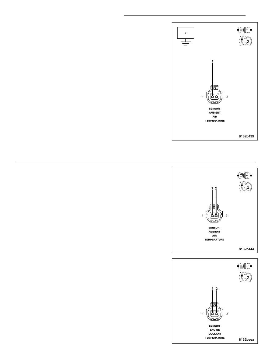
Measure the voltage on the (K2) ECT Signal circuit and the (G31) AAT
Signal circuit at the appropriate Temperature Sensor harness connector.

Is the voltage above 5.2 volts?

Yes

>> Repair the short to battery voltage in the Signal circuit.

Perform the POWERTRAIN VERIFICATION TEST. (Refer to
9 - ENGINE - STANDARD PROCEDURE)

No

>> Go To 8

8.

TEMPERATURE SENSOR

Turn the ignition off.

Connect the C2 PCM harness connector.

Connect the C2 BCM harness connector if the vehicle is equipped with
ESP.

Connect a jumper wire across the ECT and AAT Sensor harness con-
nectors.

Ignition on, engine not running.

With a scan tool, read the Temperature Sensor voltage.

Does the voltage start at 5.0 volts and drop below 1.0 volt
when the jumper wire is installed?

Yes

>> Replace the appropriate Temperature Sensor.

Perform the POWERTRAIN VERIFICATION TEST. (Refer to
9 - ENGINE - STANDARD PROCEDURE)

No

>> Go To 9

9 - 110

ENGINE ELECTRICAL DIAGNOSTICS

KJ

NOTE: Disconnect the jumper wire before continuing.

9.

SIGNAL CIRCUIT OPEN

Turn the ignition off.

CAUTION: Do not probe the PCM harness connectors. Probing the
PCM harness connectors will damage the PCM terminals resulting
in poor terminal to pin connection. Install Miller Special Tool #8815
to perform diagnosis.
Measure the resistance of the (K2) ECT Sensor Signal circuit from the
ECT Sensor harness connector to the appropriate terminal of special
tool #8815.

Measure the resistance of the (G31) AAT Sensor Signal circuit from the
AAT Sensor harness connector to the appropriate terminal of special
tool #8815.

Is the resistance below 5.0 ohms?

Yes

>> Go To 10

No

>> Repair the open in the Sensor Signal circuit.

Perform the POWERTRAIN VERIFICATION TEST. (Refer to
9 - ENGINE - STANDARD PROCEDURE)

KJ

ENGINE ELECTRICAL DIAGNOSTICS

9 - 111

10.

SENSOR GROUND CIRCUIT OPEN

Measure the resistance of the (K900) Sensor ground circuit from the
appropriate Temperature Sensor harness connector to the appropriate
terminal of special tool #8815.

Measure the resistance of the (K300) Sensor ground circuit from AAT
Sensor harness connector to the C2 BCM harness connector for ESP
equipped vehicles.

Is the resistance below 5.0 ohms?

Yes

>> Go To 11

No

>> Repair the open in the Sensor ground circuit.

Perform the POWERTRAIN VERIFICATION TEST. (Refer to
9 - ENGINE - STANDARD PROCEDURE)

9 - 112

ENGINE ELECTRICAL DIAGNOSTICS

KJ

11.

SIGNAL CIRCUIT SHORTED TO GROUND

Measure the resistance between ground and the Sensor Signal circuit in
the Temperature Sensor harness connector.

Is the resistance below 100 ohms?

Yes

>> Repair the short to ground in the Signal circuit.

Perform the POWERTRAIN VERIFICATION TEST. (Refer to
9 - ENGINE - STANDARD PROCEDURE)

No

>> Go To 12

KJ

ENGINE ELECTRICAL DIAGNOSTICS

9 - 113


Content   ..  486  487  488  489   ..