Jeep Liberty KJ. Manual - part 476
3.
MAP SENSOR
With a scan tool, monitor the MAP Sensor voltage with the Sensor harness connector disconnected.
Is the voltage above 4.5 volts?
Yes
>> Replace the MAP Sensor.
Perform the POWERTRAIN VERIFICATION TEST. (Refer to 9 - ENGINE - STANDARD PROCEDURE)
No
>> Go To 4
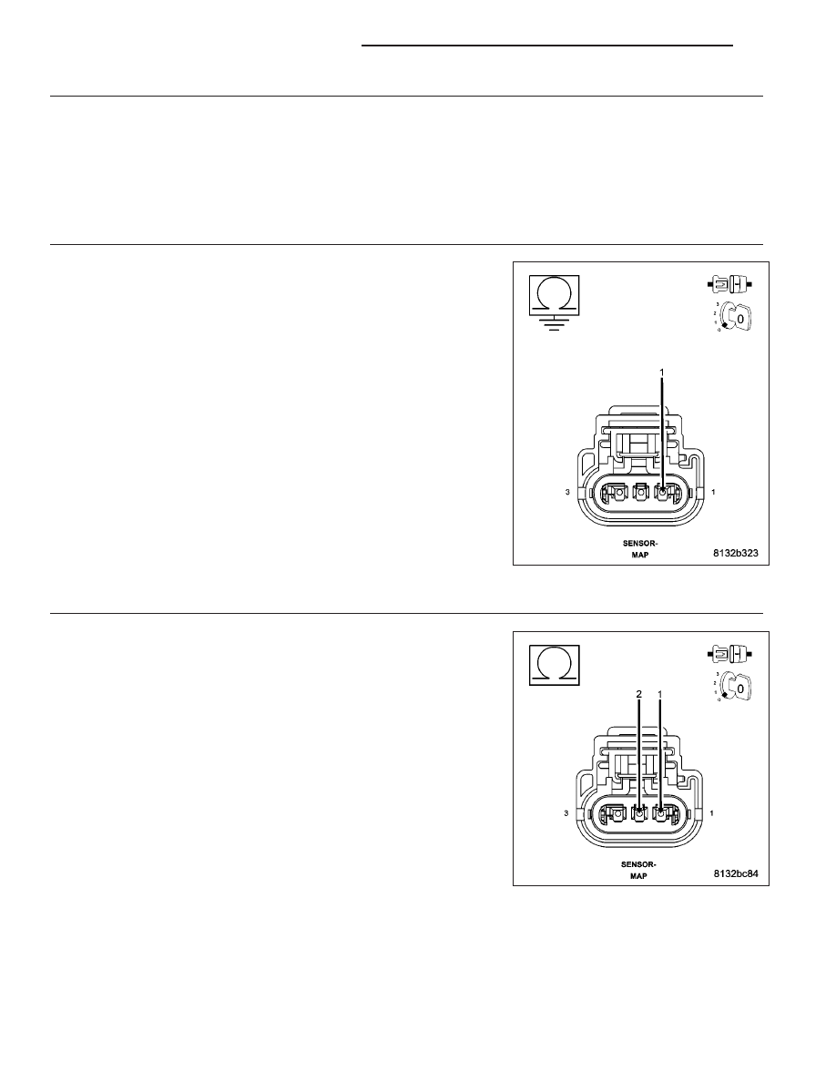
4.
(K1) MAP SIGNAL CIRCUIT SHORTED TO GROUND
Turn the ignition off.
Disconnect the C2 PCM harness connector.
Measure the resistance between ground and the (K1) MAP Signal cir-
cuit in the MAP Sensor harness connector.
Is the resistance below 100 ohms?
Yes
>> Repair the short to ground in the (K1) MAP Signal circuit.
Perform the POWERTRAIN VERIFICATION TEST. (Refer to
9 - ENGINE - STANDARD PROCEDURE)
No
>> Go To 5
5.
(K1) MAP SIGNAL CIRCUIT SHORTED TO THE (K900) SENSOR GROUND CIRCUIT
Measure the resistance between the (K1) MAP Signal circuit and the
(K900) Sensor ground circuit in the MAP Sensor harness connector.
Is the resistance below 100 ohms?
Yes
>> Repair the short between the (K900) Sensor ground and the
(K1) MAP Signal circuit.
Perform the POWERTRAIN VERIFICATION TEST. (Refer to
9 - ENGINE - STANDARD PROCEDURE)
No
>> Go To 8
9 - 62
ENGINE ELECTRICAL DIAGNOSTICS
KJ