Jeep Liberty KJ. Manual - part 328
•
When Monitored:
With the ignition on.
•
Set Condition:
The Hands Free Module detects high voltage on the (X793) Microphone Feed circuit.
Possible Causes
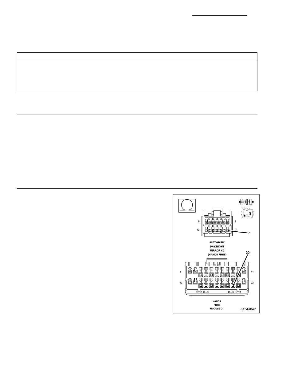
(X793) MICROPHONE FEED CIRCUIT OPEN
(X793) MICROPHONE FEED CIRCUIT SHORT TO VOLTAGE
AUTOMATIC DAY/NIGHT MIRROR
HANDS FREE MODULE
Diagnostic Test
1.
CHECK FOR ACTIVE DTC
Turn the ignition on.
With the scan tool, erase the HFM DTCs.
Attempt to make a phone call using the system.
With the scan tool, read the HFM DTCs.
Did this DTC reset?
Yes
>> Go To 2
No
>> The condition that set this DTC is no longer present. Using the wiring diagram/schematic as a guide,
inspect the wiring for chafed, pierced, pinched, and partially broken wires and the wiring harness con-
nectors for broken, bent, pushed out, and corroded terminals.
2.
(X793) MICROPHONE FEED CIRCUIT OPEN
Turn the ignition off.
Disconnect the Hands Free Module C1 harness connector.
Disconnect the Automatic Day/Night Mirror C2 harness connector.
Measure the resistance of the (X793) Microphone Feed circuit between
the HFM connector and the Automatic Day/Night Mirror connector.
Is the resistance below 5.0 ohms?
Yes
>> Go To 3
No
>> Repair the (X793) Microphone Feed circuit for an open.
Perform BODY VERIFICATION TEST – VER 1. (Refer to 8
-
ELECTRICAL/ELECTRONIC
CONTROL MODULES
-
STANDARD PROCEDURE).
8T - 34
NAVIGATION/TELECOMMUNICATION - ELECTRICAL DIAGNOSTICS
KJ